Model 101

This is a standard-size lineup of electromagnetically operated clutches that activate when an electric current is applied to the coil. Designed for space-efficient flange mounting, the lineup includes three types of armature assemblies with different mounting configurations, allowing you to select the one that best suits your installation requirements.
[Specifications]
| Model | Size | Dynamic friction torque Td [N·m] | Static friction torque Ts [N·m] | Coil (at 20°C) | Temperature Rating | Lead wire | Maximum rotational speed [min⁻¹] | Rotating Mass Moment of Inertia J | Total work until air gap readjustment ET [J] | Armature suction time ta [s] | Torque rise time tp [s] | Torque decay time td [s] | Mass [kg] | |||||
|---|---|---|---|---|---|---|---|---|---|---|---|---|---|---|---|---|---|---|
| Voltage [V] | Power [W] | Current [A] | Resistance [Ω] | UL Style | Size | Maximum Rotor Speed [kg·m²] | Maximum Armature Speed [kg·m²] | |||||||||||
| 101-06-13G | 06 | 5 | 5.5 | 24 DC | 11 | 0.46 | 52 | B | UL3398 | AWG 22 | 8000 | 7.35×10⁻⁵ | 4.23×10⁻⁵ | 36×10⁶ | 0.020 | 0.041 | 0.020 | 0.46 |
| 101-06-15G | 06 | 5 | 5.5 | 24 DC | 11 | 0.46 | 52 | B | UL3398 | AWG 22 | 8000 | 7.35×10⁻⁵ | 1.05×10⁻⁴ | 36×10⁶ | 0.020 | 0.041 | 0.020 | 0.66 |
| 101-06-11G | 06 | 5 | 5.5 | 24 DC | 11 | 0.46 | 52 | B | UL3398 | AWG 22 | 8000 | 7.35×10⁻⁵ | 6.03×10⁻⁵ | 36×10⁶ | 0.020 | 0.041 | 0.020 | 0.5 |
| 101-08-13G | 08 | 10 | 11 | 24 DC | 15 | 0.63 | 38 | B | UL3398 | AWG 18 | 6000 | 2.24×10⁻⁴ | 1.18×10⁻⁴ | 60×10⁶ | 0.023 | 0.051 | 0.030 | 0.83 |
| 101-08-15G | 08 | 10 | 11 | 24 DC | 15 | 0.63 | 38 | B | UL3398 | AWG 18 | 6000 | 2.24×10⁻⁴ | 3.00×10⁻⁴ | 60×10⁶ | 0.023 | 0.051 | 0.030 | 1.19 |
| 101-08-11G | 08 | 10 | 11 | 24 DC | 15 | 0.63 | 38 | B | UL3398 | AWG 18 | 6000 | 2.24×10⁻⁴ | 1.71×10⁻⁴ | 60×10⁶ | 0.023 | 0.051 | 0.030 | 0.91 |
| 101-10-13G | 10 | 20 | 22 | 24 DC | 20 | 0.83 | 29 | B | UL3398 | AWG 18 | 5000 | 6.78×10⁻⁴ | 4.78×10⁻⁴ | 130×10⁶ | 0.025 | 0.063 | 0.050 | 1.5 |
| 101-10-15G | 10 | 20 | 22 | 24 DC | 20 | 0.83 | 29 | B | UL3398 | AWG 18 | 5000 | 6.78×10⁻⁴ | 9.45×10⁻⁴ | 130×10⁶ | 0.025 | 0.063 | 0.050 | 2.11 |
| 101-10-11G | 10 | 20 | 22 | 24 DC | 20 | 0.83 | 29 | B | UL3398 | AWG 18 | 5000 | 6.78×10⁻⁴ | 6.63×10⁻⁴ | 130×10⁶ | 0.025 | 0.063 | 0.050 | 1.66 |
| 101-12-13G | 12 | 40 | 45 | 24 DC | 25 | 1.04 | 23 | B | UL3398 | AWG 18 | 4000 | 2.14×10⁻³ | 1.31×10⁻³ | 250×10⁶ | 0.040 | 0.115 | 0.065 | 2.76 |
| 101-12-15G | 12 | 40 | 45 | 24 DC | 25 | 1.04 | 23 | B | UL3398 | AWG 18 | 4000 | 2.14×10⁻³ | 2.75×10⁻³ | 250×10⁶ | 0.040 | 0.115 | 0.065 | 3.8 |
| 101-12-11G | 12 | 40 | 45 | 24 DC | 25 | 1.04 | 23 | B | UL3398 | AWG 18 | 4000 | 2.14×10⁻³ | 1.81×10⁻³ | 250×10⁶ | 0.040 | 0.115 | 0.065 | 3.05 |
| 101-16-13G | 16 | 80 | 90 | 24 DC | 35 | 1.46 | 16 | B | UL3398 | AWG 18 | 3000 | 6.30×10⁻³ | 4.80×10⁻³ | 470×10⁶ | 0.050 | 0.160 | 0.085 | 5.1 |
| 101-16-15G | 16 | 80 | 90 | 24 DC | 35 | 1.46 | 16 | B | UL3398 | AWG 18 | 3000 | 6.30×10⁻³ | 9.05×10⁻³ | 470×10⁶ | 0.050 | 0.160 | 0.085 | 6.9 |
| 101-16-11G | 16 | 80 | 90 | 24 DC | 35 | 1.46 | 16 | B | UL3398 | AWG 18 | 3000 | 6.30×10⁻³ | 6.35×10⁻³ | 470×10⁶ | 0.050 | 0.160 | 0.085 | 5.4 |
| 101-20-13G | 20 | 160 | 175 | 24 DC | 45 | 1.88 | 13 | B | UL3398 | AWG 16 | 2500 | 1.93×10⁻² | 1.37×10⁻² | 10×10⁸ | 0.090 | 0.250 | 0.130 | 9.3 |
| 101-20-15G | 20 | 160 | 175 | 24 DC | 45 | 1.88 | 13 | B | UL3398 | AWG 16 | 2500 | 1.93×10⁻² | 2.65×10⁻² | 10×10⁸ | 0.090 | 0.250 | 0.130 | 13 |
| 101-20-11G | 20 | 160 | 175 | 24 DC | 45 | 1.88 | 13 | B | UL3398 | AWG 16 | 2500 | 1.93×10⁻² | 1.90×10⁻² | 10×10⁸ | 0.090 | 0.250 | 0.130 | 10.5 |
| 101-25-13G | 25 | 320 | 350 | 24 DC | 60 | 2.5 | 9.6 | B | UL3398 | AWG 16 | 2000 | 4.48×10⁻² | 3.58×10⁻² | 20×10⁸ | 0.115 | 0.335 | 0.210 | 17 |
| 101-25-15G | 25 | 320 | 350 | 24 DC | 60 | 2.5 | 9.6 | B | UL3398 | AWG 16 | 2000 | 4.48×10⁻² | 7.45×10⁻² | 20×10⁸ | 0.115 | 0.335 | 0.210 | 23.6 |
| 101-25-11G | 25 | 320 | 350 | 24 DC | 60 | 2.5 | 9.6 | B | UL3398 | AWG 16 | 2000 | 4.48×10⁻² | 4.83×10⁻² | 20×10⁸ | 0.115 | 0.335 | 0.210 | 18.7 |
- The dynamic friction torque Td is the value at a relative speed of 100 min⁻¹. Additionally, depending on the initial torque characteristics, a break-in period may be required.
- The moment of inertia and mass of the rotating section are based on the maximum bore diameter.
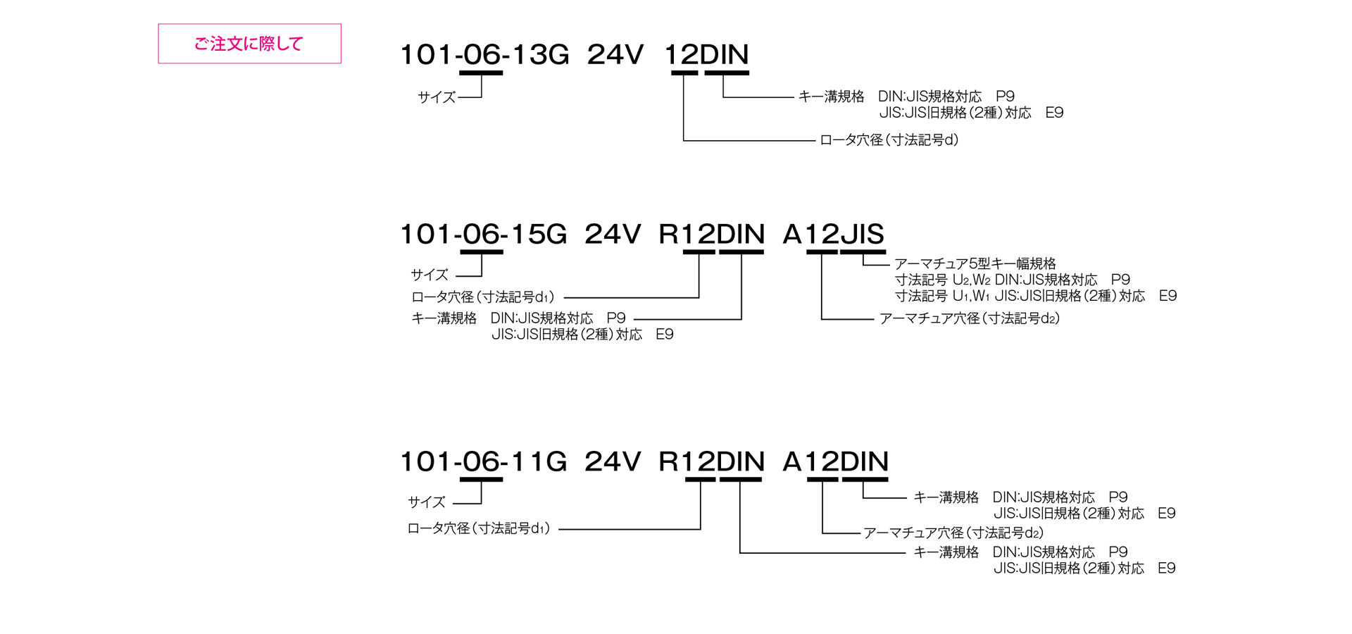
[Dimensions] 101-□-13G
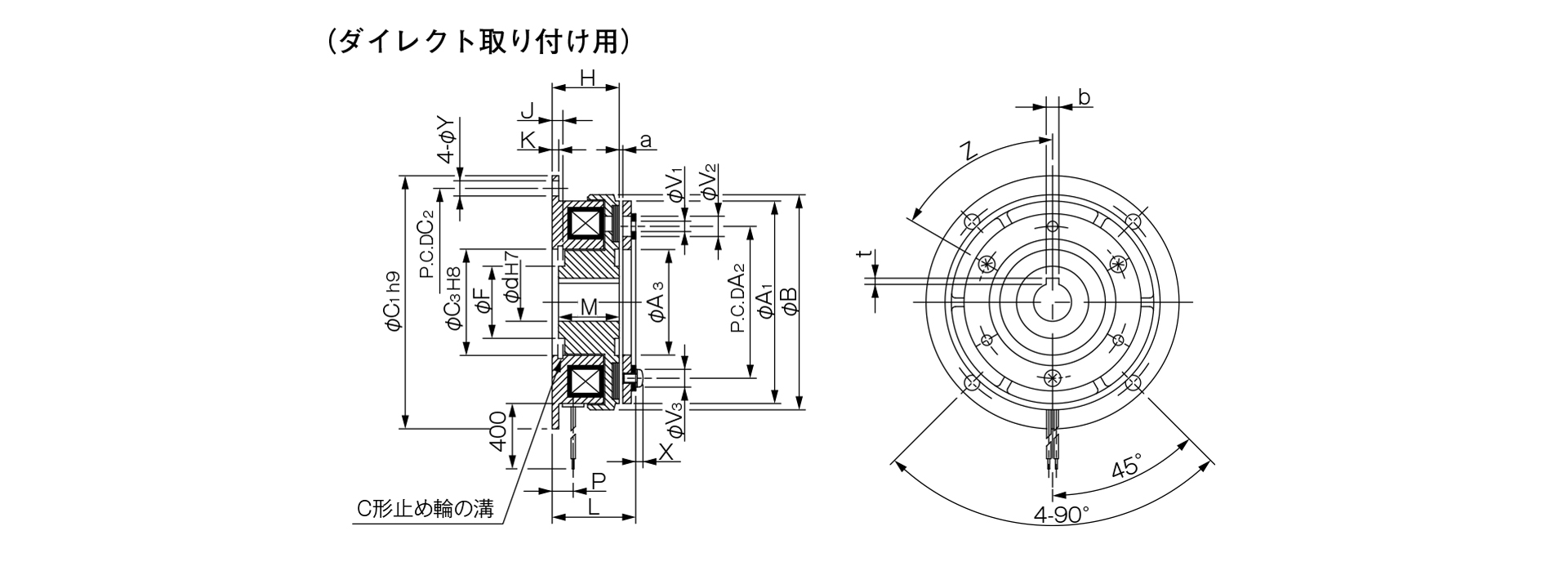
Unit [mm]
| Size | Radial dimensions | Axial dimensions | |||||||||||||||||||||||
|---|---|---|---|---|---|---|---|---|---|---|---|---|---|---|---|---|---|---|---|---|---|---|---|---|---|
| A | B | C1 | C2 | C3 | E | F | Y | S | Z1 | Z2 | H | J | K | L | M | N1 | N2 | P | U1 | W1 | U2 | W2 | a | m | |
| 06 | 63 | 67.5 | 80 | 72 | 35 | 33 | 23 | 5 | 38 | 3–120° | 60° | 24 | 3.5 | 2.1 | 51.5 | 22 | 20 | 2 | 7.3 | 39.5 | 4 | 39.5 | 4 | 0.2–±0.05 | 3-M4×0.7 Depth 4 |
| 08 | 80 | 85 | 100 | 90 | 42 | 37 | 28.5 | 6 | 45 | 3–120° | 60° | 26.5 | 4.3 | 2.6 | 60 | 24 | 25 | 2 | 8.3 | 47 | 5 | 47 | 5 | 0.2–±0.05 | 3-M4×0.7 Depth 6 |
| 10 | 100 | 106 | 125 | 112 | 52 | 47 | 40 | 7 | 55 | 4–90° | 45° | 30 | 5 | 3.1 | 71.1 | 27 | 30 | 3 | 9 | 57 | 5 | 57.5 | 6 | 0.2–±0.05 | 4-M4×0.7 Depth 8 |
| 12 | 125 | 133 | 150 | 137 | 62 | 52 | 45 | 7 | 64 | 4–90° | 45° | 33.5 | 5.5 | 3.6 | 86.5 | 30 | 40 | 2.2 | 9.3 | 67 | 7 | 67 | 8 | 0.3 + 0.05 – 0.1 | 4-M4×0.7 Depth 8 |
| 16 | 160 | 169 | 190 | 175 | 80 | 62 | 62 | 9.5 | 75 | 6–60° | 30° | 37.5 | 6 | 4.1 | 103.5 | 34 | 50 | 3 | 11.7 | 78 | 7 | 78 | 8 | 0.3 + 0.05 – 0.1 | 6-M5×0.8 Depth 8 |
| 20 | 200 | 212.3 | 230 | 215 | 100 | 74.5 | 77 | 9.5 | 90 | 4–90° | 45° | 44 | 7 | 5.1 | 124.4 | 40 | 60 | 5 | 13.4 | 93.5 | 10 | 93 | 10 | 0.50–0.2 | 4-M6×1 Depth 12 |
| 25 | 250 | 264 | 290 | 270 | 125 | 101.5 | 100 | 11.5 | 115 | 8–45° | 22.5° | 51 | 8 | 6.1 | 144.9 | 47 | 70 | 6 | 16 | 118.5 | 12 | 118 | 12 | 0.50–0.2 | 8-M6×1 Depth 12 |
Unit [mm]
| Size | Shaft hole dimensions | ||||
|---|---|---|---|---|---|
| d1H7 | Compliant with JIS standards | Compatible with Old JIS Standards | |||
| d1H7 | bP9 | t | bE9 | t | |
| 06 | 12 | 4–0.012–0.042 | 1.5 + 0.50 | 4 + 0.050 + 0.020 | 1.5 + 0.50 |
| 08 | 15 | 5–0.012–0.042 | 2 + 0.50 | 5 + 0.050 + 0.020 | 2 + 0.50 |
| 10 | 20 | 6–0.012–0.042 | 2.5 + 0.50 | 5 + 0.050 + 0.020 | 2 + 0.50 |
| 12 | 25 | 8–0.015–0.051 | 3 + 0.50 | 7 + 0.061 + 0.025 | 3 + 0.50 |
| 16 | 30 | 8 - 0.015 - 0.051 | 3 + 0.50 | 7 + 0.061 + 0.025 | 3 + 0.50 |
| 20 | 40 | 12–0.018–0.061 | 3 + 0.50 | 10 + 0.061 + 0.025 | 3.5 + 0.50 |
| 25 | 50 | 14–0.018–0.061 | 3.5 + 0.50 | 12 + 0.075 + 0.032 | 3.5 + 0.50 |
- For information regarding installation methods and other details, please refer to the design specifications.
[Dimensions] 101-□-15G
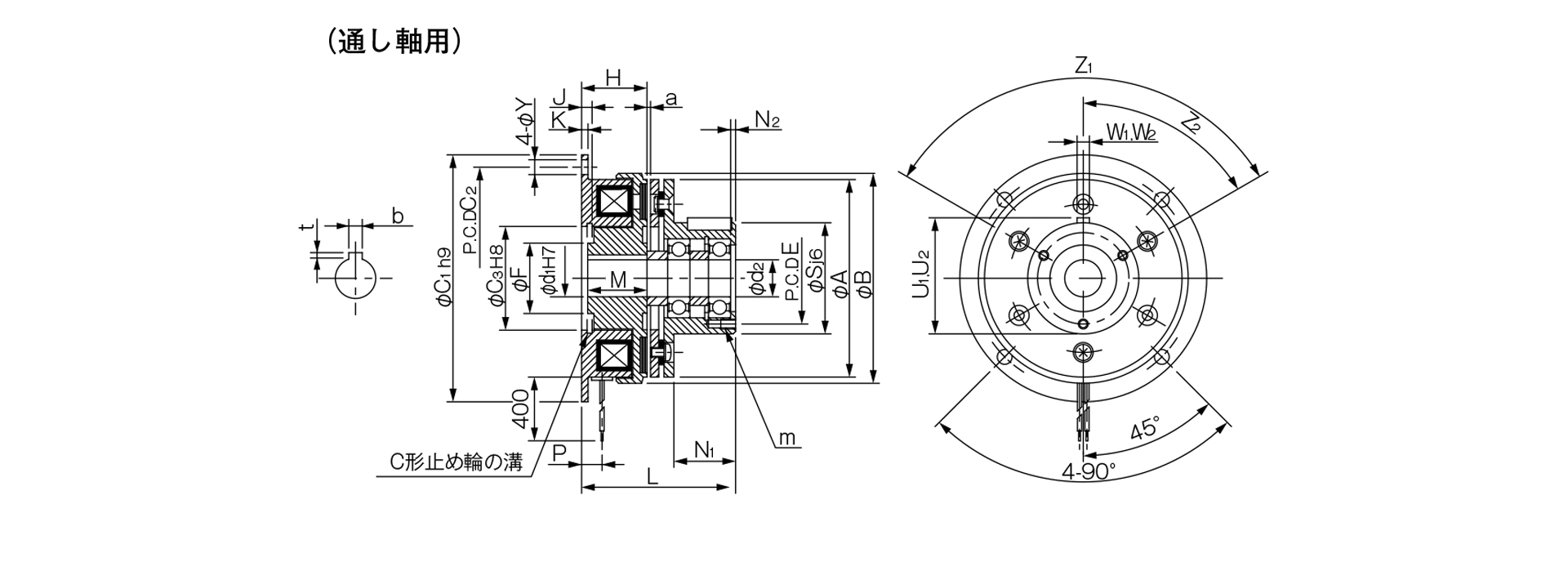
Unit [mm]
| Size | Radial dimensions | Axial dimensions | |||||||||||||||||||||||
|---|---|---|---|---|---|---|---|---|---|---|---|---|---|---|---|---|---|---|---|---|---|---|---|---|---|
| A | B | C1 | C2 | C3 | E | F | Y | S | Z1 | Z2 | H | J | K | L | M | N1 | N2 | P | U1 | W1 | U2 | W2 | a | m | |
| 06 | 63 | 67.5 | 80 | 72 | 35 | 33 | 23 | 5 | 38 | 3–120° | 60° | 24 | 3.5 | 2.1 | 51.5 | 22 | 20 | 2 | 7.3 | 39.5 | 4 | 39.5 | 4 | 0.2–±0.05 | 3-M4×0.7 Depth 4 |
| 08 | 80 | 85 | 100 | 90 | 42 | 37 | 28.5 | 6 | 45 | 3–120° | 60° | 26.5 | 4.3 | 2.6 | 60 | 24 | 25 | 2 | 8.3 | 47 | 5 | 47 | 5 | 0.2–±0.05 | 3-M4×0.7 Depth 6 |
| 10 | 100 | 106 | 125 | 112 | 52 | 47 | 40 | 7 | 55 | 4–90° | 45° | 30 | 5 | 3.1 | 71.1 | 27 | 30 | 3 | 9 | 57 | 5 | 57.5 | 6 | 0.2–±0.05 | 4-M4×0.7 Depth 8 |
| 12 | 125 | 133 | 150 | 137 | 62 | 52 | 45 | 7 | 64 | 4–90° | 45° | 33.5 | 5.5 | 3.6 | 86.5 | 30 | 40 | 2.2 | 9.3 | 67 | 7 | 67 | 8 | 0.3 + 0.05 – 0.1 | 4-M4×0.7 Depth 8 |
| 16 | 160 | 169 | 190 | 175 | 80 | 62 | 62 | 9.5 | 75 | 6–60° | 30° | 37.5 | 6 | 4.1 | 103.5 | 34 | 50 | 3 | 11.7 | 78 | 7 | 78 | 8 | 0.3 + 0.05 – 0.1 | 6-M5×0.8 Depth 8 |
| 20 | 200 | 212.3 | 230 | 215 | 100 | 74.5 | 77 | 9.5 | 90 | 4–90° | 45° | 44 | 7 | 5.1 | 124.4 | 40 | 60 | 5 | 13.4 | 93.5 | 10 | 93 | 10 | 0.50–0.2 | 4-M6×1 Depth 12 |
| 25 | 250 | 264 | 290 | 270 | 125 | 101.5 | 100 | 11.5 | 115 | 8–45° | 22.5° | 51 | 8 | 6.1 | 144.9 | 47 | 70 | 6 | 16 | 118.5 | 12 | 118 | 12 | 0.50–0.2 | 8-M6×1 Depth 12 |
Unit [mm]
| Size | Shaft hole dimensions | |||||
|---|---|---|---|---|---|---|
| d1 H7 | d2 | Compliant with JIS standards | Compatible with old JIS standards | |||
| d1H7 | bP9 | t | bE9 | t | ||
| 06 | 12 | 12 | 4–0.012–0.042 | 1.5 + 0.50 | 4 + 0.050 + 0.020 | 1.5 + 0.50 |
| 08 | 15 | 15 | 5–0.012–0.042 | 2 + 0.50 | 5 + 0.050 + 0.020 | 2 + 0.50 |
| 10 | 20 | 20 | 6–0.012–0.042 | 2.5 + 0.50 | 5 + 0.050 + 0.020 | 2 + 0.50 |
| 12 | 25 | 25 | 8–0.015–0.051 | 3 + 0.50 | 7 + 0.061 + 0.025 | 3 + 0.50 |
| 16 | 30 | 30 | 8–0.015–0.051 | 3 + 0.50 | 7 + 0.061 + 0.025 | 3 + 0.50 |
| 20 | 40 | 40 | 12–0.018–0.061 | 3 + 0.50 | 10 + 0.061 + 0.025 | 3.5 + 0.50 |
| 25 | 50 | 50 | 14–0.018–0.061 | 3.5 + 0.50 | 12 + 0.075 + 0.032 | 3.5 + 0.50 |
- For information regarding installation methods and other details, please refer to the design specifications.
[Dimensions] 101-□-11G
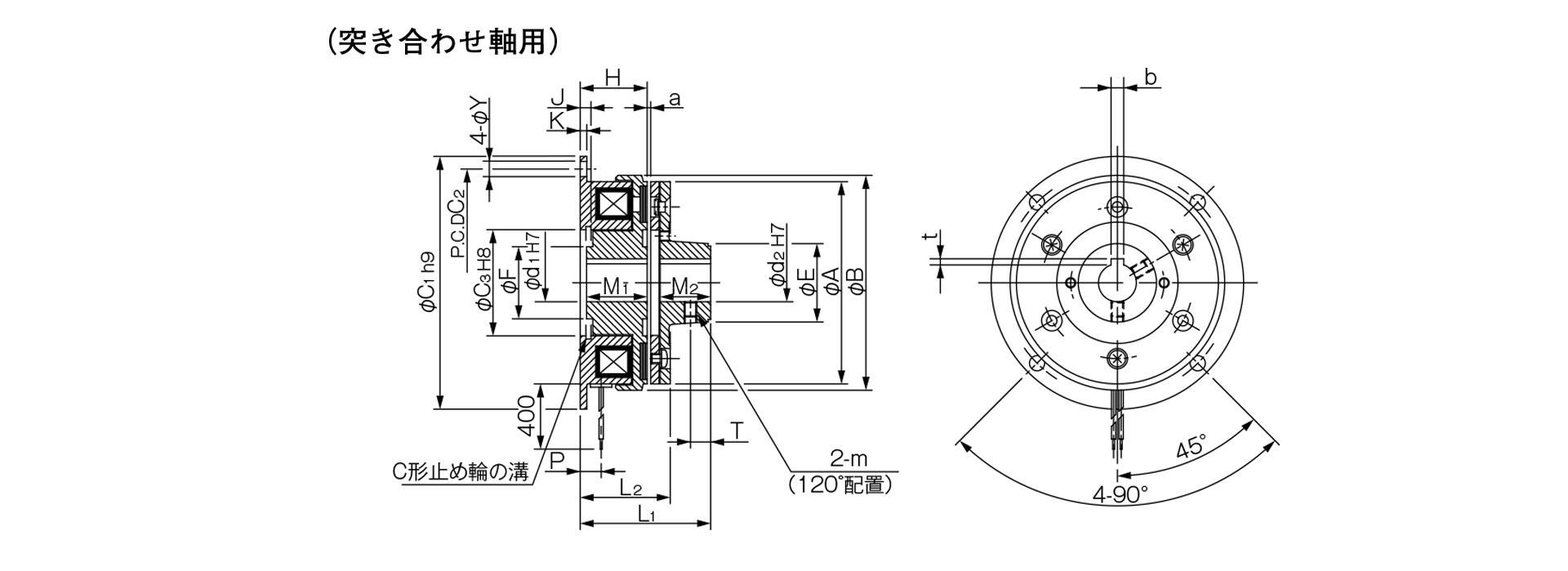
Unit [mm]
| Size | Radial dimensions | Axial dimensions | |||||||||||||||||
|---|---|---|---|---|---|---|---|---|---|---|---|---|---|---|---|---|---|---|---|
| A | B | C1 | C2 | C3 | E | F | Y | m | H | J | K | L1 | L2 | M1 | M2 | P | T | a | |
| 06 | 63 | 67.5 | 80 | 72 | 35 | 26 | 23 | 5 | M4 | 24 | 3.5 | 2.1 | 43 | 31.5 | 22 | 15 | 7.3 | 6 | 0.2–±0.05 |
| 08 | 80 | 85 | 100 | 90 | 42 | 31 | 28.5 | 6 | M5 | 26.5 | 4.3 | 2.6 | 51 | 35 | 24 | 20 | 8.3 | 8 | 0.2–±0.05 |
| 10 | 100 | 106 | 125 | 112 | 52 | 41 | 40 | 7 | M5 | 30 | 5 | 3.1 | 61.1 | 41.1 | 27 | 25 | 9 | 10 | 0.2–±0.05 |
| 12 | 125 | 133 | 150 | 137 | 62 | 49 | 45 | 7 | M6 | 33.5 | 5.5 | 3.6 | 70.5 | 46.5 | 30 | 30 | 9.3 | 12 | 0.3 + 0.05 - 0.1 |
| 16 | 160 | 169 | 190 | 175 | 80 | 65 | 62 | 9.5 | M8 | 37.5 | 6 | 4.1 | 84.5 | 53.5 | 34 | 38 | 11.7 | 15 | 0.3 + 0.05 - 0.1 |
| 20 | 200 | 212.3 | 230 | 215 | 100 | 83 | 77 | 9.5 | M8 | 44 | 7 | 5.1 | 100.4 | 64.4 | 40 | 45 | 13.4 | 18 | 0.50–0.2 |
| 25 | 250 | 264 | 290 | 270 | 125 | 105 | 100 | 11.5 | M10 | 51 | 8 | 6.1 | 118 | 75 | 47 | 54 | 16 | 22 | 0.50–0.2 |
Unit [mm]
| Size | Shaft Bore Dimensions | |||||
|---|---|---|---|---|---|---|
| d1H7 | d2H7 | Compliant with JIS standards | Compatible with old JIS standards | |||
| d1H7 | bP9 | t | bE9 | t | ||
| 06 | 12 | 12 | 4–0.012–0.042 | 1.5 + 0.50 | 4 + 0.050 + 0.020 | 1.5 + 0.50 |
| 15 | 15 | 5–0.012–0.042 | 2 + 0.50 | 5 + 0.050 + 0.020 | 2 + 0.50 | |
| 08 | 15 | 15 | 5–0.012–0.042 | 2 + 0.50 | 5 + 0.050 + 0.020 | 2 + 0.50 |
| 20 | 20 | 6–0.012–0.042 | 2.5 + 0.50 | 5 + 0.050 + 0.020 | 2 + 0.50 | |
| 10 | 20 | 20 | 6–0.012–0.042 | 2.5 + 0.50 | 5 + 0.050 + 0.020 | 2 + 0.50 |
| 25 | 25 | 8–0.015–0.051 | 3 + 0.50 | 7 + 0.061 + 0.025 | 3 + 0.50 | |
| 12 | 25 | 25 | 8–0.015–0.051 | 3 + 0.50 | 7 + 0.061 + 0.025 | 3 + 0.50 |
| 30 | 30 | 8–0.015–0.051 | 3 + 0.50 | 7 + 0.061 + 0.025 | 3 + 0.50 | |
| 16 | 30 | 30 | 8–0.015–0.051 | 3 + 0.50 | 7 + 0.061 + 0.025 | 3 + 0.50 |
| 40 | 40 | 12–0.018–0.061 | 3 + 0.50 | 10 + 0.061 + 0.025 | 3.5 + 0.50 | |
| 20 | 40 | 40 | 12–0.018–0.061 | 3 + 0.50 | 10 + 0.061 + 0.025 | 3.5 + 0.50 |
| 50 | 50 | 14–0.018–0.061 | 3.5 + 0.50 | 12 + 0.075 + 0.032 | 3.5 + 0.50 | |
| 25 | 50 | 50 | 14–0.018–0.061 | 3.5 + 0.50 | 12 + 0.075 + 0.032 | 3.5 + 0.50 |
| 60 | 60 | 18–0.018–0.061 | 4 + 0.50 | 15 + 0.075 + 0.032 | 5 + 0.50 | |
- For information regarding installation methods, please refer to the design specifications.