Type 102 (13, 15, 11)

This is a micro-sized lineup of electromagnetically operated clutches that activate when current is applied to the coil. Designed for space-efficient flange mounting, the series offers three types of armature assemblies with different mounting configurations, allowing you to select the one that best suits your installation requirements.
[Specifications] For direct installation
| Model | Size | Static Friction Torque Td [N·m] | Coil (at 20°C) | Lead wire | Temperature Class | Maximum rotational speed [min⁻¹] | Rotating mass moment of inertia J | Allowable coupling work Eeaℓ [J] | Total work until air gap readjustment ET [J] | Armature attraction time ta [s] | Torque rise time tp [s] | Torque decay time td [s] | Mass [kg] | |||||
|---|---|---|---|---|---|---|---|---|---|---|---|---|---|---|---|---|---|---|
| Voltage [V] | Power [W] | Current [A] | Resistance [Ω] | UL Style | Size | Armature [kg·m²] | Rotor [kg·m²] | |||||||||||
| 02/13/2010 | 2 | 0.4 | DC24 | 6 | 0.25 | 96 | UL3398 | AWG 26 | B | 10,000 | 6.75×10⁻⁷ | 2.45×10⁻⁶ | 1500 | 2×10⁶ | 0.009 | 0.019 | 0.017 | 0.075 |
| February 15, 2010 | 2 | 0.4 | DC24 | 6 | 0.25 | 96 | UL3398 | AWG 26 | B | 500 | 1.00×10⁻⁶ | 2.45×10⁻⁶ | 1500 | 2×10⁶ | 0.009 | 0.019 | 0.017 | 0.081 |
| February 11, 2010 | 2 | 0.4 | DC24 | 6 | 0.25 | 96 | UL3398 | AWG 26 | B | 10,000 | 1.00×10⁻⁶ | 2.45×10⁻⁶ | 1500 | 2×10⁶ | 0.009 | 0.019 | 0.017 | 0.079 |
| March 13, 2010 | 3 | 0.6 | DC24 | 6 | 0.25 | 96 | UL3398 | AWG 26 | B | 10,000 | 1.30×10⁻⁶ | 3.25×10⁻⁶ | 2300 | 3×10⁶ | 0.009 | 0.022 | 0.02 | 0.096 |
| March 15, 2010 | 3 | 0.6 | DC24 | 6 | 0.25 | 96 | UL3398 | AWG 26 | B | 500 | 1.95×10⁻⁶ | 3.25×10⁻⁶ | 2300 | 3×10⁶ | 0.009 | 0.022 | 0.02 | 0.105 |
| March 11, 2010 | 3 | 0.6 | DC24 | 6 | 0.25 | 96 | UL3398 | AWG 26 | B | 10,000 | 1.95×10⁻⁶ | 3.25×10⁻⁶ | 2300 | 3×10⁶ | 0.009 | 0.022 | 0.02 | 0.103 |
| April 13, 2010 | 4 | 1.2 | DC24 | 8 | 0.33 | 72 | UL3398 | AWG 26 | B | 10,000 | 4.38×10⁻⁶ | 1.41×10⁻⁵ | 4500 | 6×10⁶ | 0.011 | 0.028 | 0.03 | 0.178 |
| April 15, 2010 | 4 | 1.2 | DC24 | 8 | 0.33 | 72 | UL3398 | AWG 26 | B | 500 | 6.15×10⁻⁶ | 1.41×10⁻⁵ | 4500 | 6×10⁶ | 0.011 | 0.028 | 0.03 | 0.195 |
| April 11, 2010 | 4 | 1.2 | DC24 | 8 | 0.33 | 72 | UL3398 | AWG 26 | B | 10,000 | 6.15×10⁻⁶ | 1.41×10⁻⁵ | 4500 | 6×10⁶ | 0.011 | 0.028 | 0.03 | 0.191 |
| May 13, 2010 | 5 | 2.4 | DC24 | 10 | 0.42 | 58 | UL3398 | AWG 22 | B | 10,000 | 9.08×10⁻⁶ | 3.15×10⁻⁵ | 9000 | 9×10⁶ | 0.012 | 0.031 | 0.04 | 0.31 |
| May 15, 2010 | 5 | 2.4 | DC24 | 10 | 0.42 | 58 | UL3398 | AWG 22 | B | 500 | 1.38×10⁻⁵ | 3.15×10⁻⁵ | 9000 | 9×10⁶ | 0.012 | 0.031 | 0.04 | 0.335 |
| May 11, 2010 | 5 | 2.4 | DC24 | 10 | 0.42 | 58 | UL3398 | AWG 22 | B | 10,000 | 1.38×10⁻⁵ | 3.15×10⁻⁵ | 9000 | 9×10⁶ | 0.012 | 0.031 | 0.04 | 0.325 |
- The dynamic friction torque Td is the value at a relative speed of 100 min⁻¹. Additionally, depending on the initial torque characteristics, a break-in period may be required.
- Keep fluctuations in the supply voltage within ±10% of the coil voltage. Also, ensure that the duty cycle does not exceed 80%.
- The moment of inertia and mass of the rotating section are based on the values at the maximum bore diameter.
[Dimensions] For direct installation
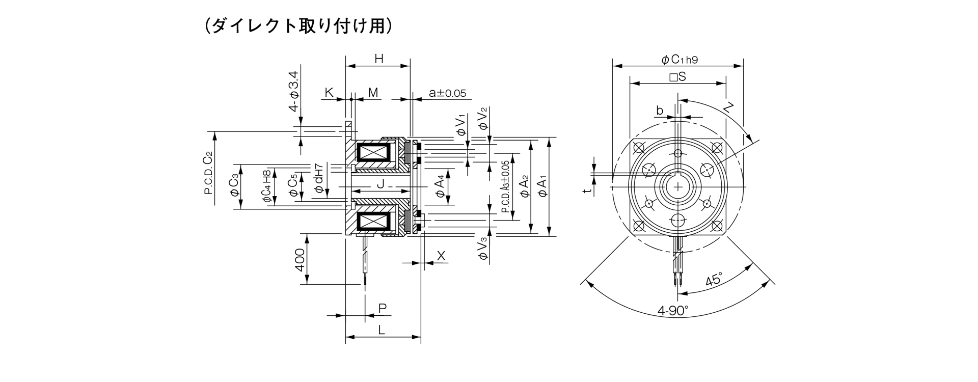
Unit [mm]
| Size | Radial dimensions | Axial dimensions | CAD File No. | ||||||||||||||||||||
|---|---|---|---|---|---|---|---|---|---|---|---|---|---|---|---|---|---|---|---|---|---|---|---|
| A1 | A2 | A3 | A4 | C1 | C2 | C3 | C4 | C5 | S | V1 | V2 | V3 | Z | H | J | K | L | P | M | a | X | ||
| 02 | 31 | 28 | 19.5 | 10.7 | 39 | 33.5 | 11.4 | 11 | 8 | - | 2–2.1 | 2–5.3 | 2-3.7 | 4–90° | 18 | 16.5 | 1.5 | 20.4 | 4.9 | 1.1 | 0.1 | 0.8 | 102–131 |
| 03 | 34 | 32 | 23 | 12.5 | 45 | 38 | 13.6 | 13 | 10 | 33 | 3-2.6 | 3-6 | 3–4.5 | 6–60° | 22.2 | 20.2 | 2 | 24.5 | 6.7 | 1.3 | 0.15 | 1.2 | 102–132 |
| 04 | 43 | 40 | 30 | 18.5 | 54 | 47 | 20 | 19 | 15.5 | 41 | 3-3.1 | 3-6 | 3-5 | 6–60° | 25.4 | 23.4 | 2 | 28.1 | 7.2 | 1.3 | 0.15 | 1.6 | 102–133 |
| 05 | 54 | 50 | 38 | 25.5 | 65 | 58 | 27.2 | 26 | 22 | 51 | 3–3.1 | 3-6.5 | 3–6 | 6–60° | 28.1 | 26.1 | 2 | 31.3 | 8.2 | 1.5 | 0.2 | 1.5 | 102–134 |
Unit [mm]
| Size | Shaft bore dimensions | ||||
|---|---|---|---|---|---|
| d1 H7 | Compliant with JIS standards | Compatible with old JIS standards | |||
| d1 H7 | b P9 | t | b E9 | t | |
| 02 | 5 | - | - | - | - |
| 03 | 6 | 2–0.006–0.031 | 0.8 + 0.30 | - | - |
| 04 | 8 | 2–0.006–0.031 | 0.8 + 0.30 | - | - |
| 10 | 3–0.006–0.031 | 1.2 + 0.30 | 4 + 0.050 + 0.020 | 1.5 + 0.50 | |
| 05 | 10 | 3–0.006–0.031 | 1.2 + 0.30 | 4 + 0.050 + 0.020 | 1.5 + 0.50 |
| 15 | 5–0.012–0.042 | 2 + 0.50 | 5 + 0.050 + 0.020 | 2 + 0.50 | |
- Size 02 is a round flange.
- The Size 02 rotor does not have a keyway. Please secure it to the shaft by press-fitting or a similar method.
- For information regarding installation methods, please refer to the design specifications.

[Dimensions] For through-shafts
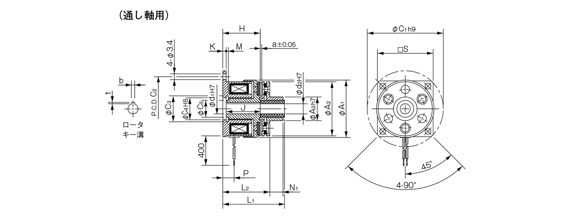
Unit [mm]
| Size | Radial dimensions | Axial dimensions | CAD File No. | ||||||||||||||||
|---|---|---|---|---|---|---|---|---|---|---|---|---|---|---|---|---|---|---|---|
| A1 | A2 | A3 | C1 | C2 | C3 | C4 | C5 | S | H | J | K | L1 | L2 | M | P | N1 | a | ||
| 02 | 31 | 28 | 13 | 39 | 33.5 | 11.4 | 11 | 8 | - | 18 | 16.5 | 1.5 | 27.5 | 22.4 | 1.1 | 4.9 | 4.8 | 0.1 | 102–151 |
| 03 | 34 | 32 | 14 | 45 | 38 | 13.6 | 13 | 10 | 33 | 22.2 | 20.2 | 2 | 34.5 | 26.5 | 1.3 | 6.7 | 7.8 | 0.15 | 102–152 |
| 04 | 43 | 40 | 18 | 54 | 47 | 20 | 19 | 15.5 | 41 | 25.4 | 23.4 | 2 | 40.2 | 30.8 | 1.3 | 7.2 | 9.1 | 0.15 | 102–153 |
| 05 | 54 | 50 | 28 | 65 | 58 | 27.2 | 26 | 22 | 51 | 28.1 | 26.1 | 2 | 43.3 | 34.3 | 1.5 | 8.2 | 8.8 | 0.2 | 102–154 |
Unit [mm]
| Size | Shaft Bore Dimensions | |||||
|---|---|---|---|---|---|---|
| d1 H7 | d2 H7 | Compliant with JIS standards | Compliant with old JIS standards | |||
| d1 H7 | b P9 | t | b E9 | t | ||
| 02 | 5 | 5 | - | - | - | - |
| 03 | 6 | 6 | 2–0.006–0.031 | 0.8 + 0.30 | - | - |
| 04 | 8 | 8 | 2–0.006–0.031 | 0.8 + 0.30 | - | - |
| 10 | 10 | 3–0.006–0.031 | 1.2 + 0.30 | 4 + 0.050 + 0.020 | 1.5 + 0.50 | |
| 05 | 10 | 10 | 3–0.006–0.031 | 1.2 + 0.30 | 4 + 0.050 + 0.020 | 1.5 + 0.50 |
| 15 | 15 | 5–0.012–0.042 | 2 + 0.50 | 5 + 0.050 + 0.020 | 2 + 0.50 | |
- Size 02 is a round flange.
- The Size 02 rotor does not have a keyway. Please secure it to the shaft by press-fitting or a similar method.
- For information regarding installation methods, please refer to the design specifications.
- The hole d2 in the Armature 5 type is a straight hole.

[Dimensions] For butt-joint shafts
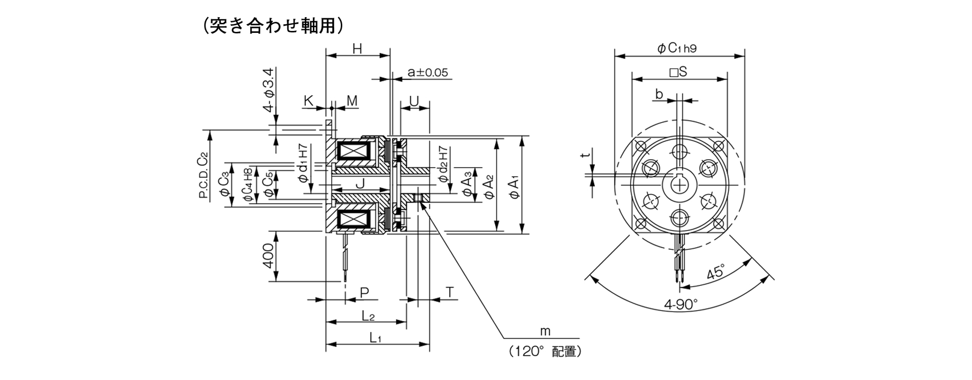
Unit [mm]
| Size | Radial dimensions | Axial dimensions | CAD File No. | ||||||||||||||||||
|---|---|---|---|---|---|---|---|---|---|---|---|---|---|---|---|---|---|---|---|---|---|
| A1 | A2 | A3 | C1 | C2 | C3 | C4 | C5 | S | m | H | J | K | L1 | L2 | M | P | U | T | a | ||
| 02 | 31 | 28 | 9.5 | 39 | 33.5 | 11.4 | 11 | 8 | - | M3 | 18 | 16.5 | 1.5 | 27.4 | 22.4 | 1.1 | 4.9 | 7 | 2.5 | 0.1 | 102–111 |
| 03 | 34 | 32 | 12 | 45 | 38 | 13.6 | 13 | 10 | 33 | 2-M3 | 22.2 | 20.2 | 2 | 34.5 | 26.5 | 1.3 | 6.7 | 10 | 4 | 0.15 | 102–112 |
| 04 | 43 | 40 | 17 | 54 | 47 | 20 | 19 | 15.5 | 41 | 2-M3 | 25.4 | 23.4 | 2 | 40.1 | 30.8 | 1.3 | 7.2 | 12 | 5 | 0.15 | 102–113 |
| 05 | 54 | 50 | 24 | 65 | 58 | 27.2 | 26 | 22 | 51 | 2-M4 | 28.1 | 26.1 | 2 | 43.3 | 34.3 | 1.5 | 8.2 | 12 | 5 | 0.2 | 102–114 |
Unit [mm]
| Size | Shaft Bore Dimensions | |||||
|---|---|---|---|---|---|---|
| d1 H7 | d2 H7 | Compliant with JIS standards | Compliant with old JIS standards | |||
| d1 H7 | b P9 | t | b E9 | t | ||
| 02 | 5 | 5 | - | - | - | - |
| 03 | 6 | 6 | 2–0.006–0.031 | 0.8 + 0.30 | - | - |
| 04 | 8 | 8 | 2–0.006–0.031 | 0.8 + 0.30 | - | - |
| 10 | 10 | 3–0.006–0.031 | 1.2 + 0.30 | 4 + 0.050 + 0.020 | 1.5 + 0.50 | |
| 05 | 10 | 10 | 3–0.006–0.031 | 1.2 + 0.30 | 4 + 0.050 + 0.020 | 1.5 + 0.50 |
| 15 | 15 | 5–0.012–0.042 | 2 + 0.50 | 5 + 0.050 + 0.020 | 2 + 0.50 | |
- Size 02 is a round flange.
- The Size 02 rotor does not have a keyway. Please secure it to the shaft by press-fitting or a similar method.
- For installation instructions and other details, please refer to the design specifications. The hole d2 on Armature Type 5 is a straight hole.