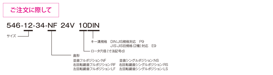
Model 546

This is an electromagnetically operated clutch that activates when an electric current is applied to the coil. Because power is transmitted through tooth engagement, it is compact yet capable of transmitting very high torque. There are two types: "full-position," which engages at any point around the circumference, and "single-position," which engages at only one specific point during a full rotation.
[Specifications]
| Model | Size | Torque [N·m] | Coil (at 20°C) | Temperature Class | Maximum connected speed [min⁻¹] | Maximum rotational speed [rpm] | Moment of inertia J [kg·m²] | Number of teeth | Armature attraction time ta [s] | Armature release time tar [s] | Bearing number | Mass [kg] | |||||||
|---|---|---|---|---|---|---|---|---|---|---|---|---|---|---|---|---|---|---|---|
| Excitation voltage [V] | Power [W] | Current [A] | Resistance [Ω] | NF | NS | Serrated | Rotor | Armature | Straight teeth Full | Full serrated | |||||||||
| 546-12-34 | 12 | 17.5 | DC24 | 13.3 | 0.55 | 43.4 | F | 50 | 30 | 100 | 1500 | 6.6×10⁻⁵ | 6.0×10⁻⁵ | 200 | 25 | 0.035 | 0.040 | 6004 | 0.5 |
| 546-13-34 | 13 | 25 | DC24 | 18.7 | 0.78 | 31.0 | F | 50 | 30 | 100 | 1500 | 1.5×10⁻⁴ | 1.2×10⁻⁴ | 220 | 30 | 0.040 | 0.050 | 6005 | 0.9 |
| 546-15-34 | 15 | 50 | DC24 | 21.3 | 0.89 | 27.1 | F | 50 | 30 | 100 | 1500 | 3.7×10⁻⁴ | 3.7×10⁻⁴ | 260 | 36 | 0.060 | 0.060 | 6007 | 1.5 |
| 546-21-34 | 21 | 100 | DC24 | 27.0 | 1.13 | 21.0 | F | 50 | 30 | 100 | 1500 | 8.7×10⁻⁴ | 5.2×10⁻⁴ | 290 | 36 | 0.080 | 0.070 | 6009 | 2.4 |
| 546-23-34 | 23 | 250 | DC24 | 36.3 | 1.51 | 15.9 | F | 50 | 30 | 100 | 1500 | 2.06×10⁻³ | 1.85×10⁻³ | 280 | 38 | 0.090 | 0.080 | 6011 | 3.9 |
| 546-25-34 | 25 | 500 | DC24 | 56.6 | 2.36 | 10.2 | F | 50 | 30 | 100 | 1500 | 4.88×10⁻³ | 4.51×10⁻³ | 250 | 40 | 0.100 | 0.090 | 6014 | 6.8 |
| 546-31-34 | 31 | 1000 | DC24 | 79.7 | 3.32 | 7.2 | F | 50 | 30 | 100 | 1500 | 1.12×10⁻² | 1.28×10⁻² | 195 | 40 | 0.110 | 0.110 | 6017 | 11.1 |
| 546-32-34 | 32 | 2200 | DC24 | 114.1 | 4.75 | 5.1 | F | 50 | 30 | 100 | 1500 | 2.87×10⁻² | 2.92×10⁻² | 186 | 40 | 0.120 | 0.130 | 6020 | 15.3 |
- The armature pickup and release times are reference values measured under no-load, stationary conditions. These times generally increase depending on the magnitude of the load and the operating conditions during connection.
- The permissible rotational speeds NF and NS represent the full-position and single-position configurations for parallel-toothed gears, respectively.
[Dimensions]
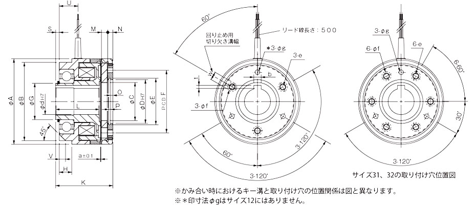
Unit [mm]
| Model | Radial Dimensions | Axial Dimensions | ||||||||||||||||||||
|---|---|---|---|---|---|---|---|---|---|---|---|---|---|---|---|---|---|---|---|---|---|---|
| A | B | C | D | E | F | G | e | f | g | H | K | L | M | N | O | P | S | U | V | W | a | |
| 546-12-34 | 57 | 52 | 22.5 | 26 | 27.2 | 36 | 20 | M4 | 8.5 | - | 10 | 43 | 34 | 4.3 | 3.1 | 1.3 | 1.3 | 2.0 | 15 | 4.5 | 5 | 0.2 |
| 546-13-34 | 67 | 58 | 31 | 32 | 33.7 | 46 | 25 | M5 | 8.5 | 4.5 | 11 | 49 | 39 | 4.9 | 3.5 | 1.4 | 1.3 | 2.5 | 16.5 | 5 | 6 | 0.3 |
| 546-15-34 | 82 | 75 | 36.5 | 42 | 44.5 | 60 | 35 | M6 | 10 | 4.5 | 12 | 55 | 42 | 6.1 | 4.8 | 2.2 | 1.9 | 3.5 | 18 | 6 | 8 | 0.3 |
| 546-21-34 | 95 | 88 | 46 | 52 | 55 | 70 | 45 | M8 | 12 | 5.5 | 14 | 63 | 45 | 8.7 | 6.0 | 2.8 | 2.2 | 3.0 | 20 | 6 | 10 | 0.4 |
| 546-23-34 | 114 | 105 | 55 | 62 | 65 | 80 | 55 | M8 | 12 | 7.8 | 18 | 69 | 50 | 9.0 | 6.5 | 3.3 | 2.2 | 3.0 | 24 | 6 | 10 | 0.4 |
| 546-25-34 | 134 | 127 | 68 | 72 | 75 | 95 | 70 | M12 | 15 | 9.5 | 20 | 83 | 61 | 11.0 | 8.4 | 4.3 | 2.7 | 3.0 | 26 | 8 | 10 | 0.4 |
| 546-31-34 | 166 | 152 | 80 | 90 | 93.5 | 120 | 85 | M12 | 15 | 9.5 | 22 | 93.5 | 66 | 13.1 | 11.4 | 5.3 | 3.2 | 3.5 | 31 | 10 | 12 | 0.5 |
| 546-32-34 | 195 | 175 | 95 | 100 | 103.5 | 150 | 100 | M12 | 19 | 11.5 | 24 | 110 | 80 | 14.0 | 11.7 | 6.3 | 3.2 | 4.0 | 38.5 | 10 | 12 | 0.5 |
Unit [mm]
| Size | Shaft Bore Dimensions | ||||
|---|---|---|---|---|---|
| d H7 | Compliant with JIS standards | Compliant with Old JIS Standards | |||
| d H7 | b P9 | t+0.50 | b E9 | t+0.50 | |
| 12 | 10 | 3–0.006–0.031 | 1.2 | 4 + 0.05 + 0.02 | 1.5 |
| 13 | 15 | 5–0.012–0.042 | 2 | 5 + 0.05 + 0.02 | 2 |
| 15 | 20 | 6–0.012–0.042 | 2.5 | 5 + 0.05 + 0.02 | 2 |
| 25 | 8–0.015–0.051 | 3 | 7 + 0.061 + 0.025 | 3 | |
| 21 | 25 | 8–0.015–0.051 | 3 | 7 + 0.061 + 0.025 | 3 |
| 30 | 8–0.015–0.051 | 3 | 7 + 0.061 + 0.025 | 3 | |
| 23 | 30 | 8–0.015–0.051 | 3 | 7 + 0.061 + 0.025 | 3 |
| 40 | 12–0.018–0.061 | 3 | 10 + 0.061 + 0.025 | 3.5 | |
| 25 | 40 | 12–0.018–0.061 | 3 | 10 + 0.061 + 0.025 | 3.5 |
| 50 | 14–0.018–0.061 | 3.5 | 12 + 0.075 + 0.032 | 3.5 | |
| 31 | 50 | 14–0.018–0.061 | 3.5 | 12 + 0.075 + 0.032 | 3.5 |
| 60 | 18–0.018–0.061 | 4 | 15 + 0.075 + 0.032 | 5 | |
| 32 | 60 | 18–0.018–0.061 | 4 | 15 + 0.075 + 0.032 | 5 |
| 70 | 20–0.022–0.074 | 4.5 | 18 + 0.075 + 0.032 | 6 | |
- 3. Unordered List (Asterisks) - 2