Model 126-4F: Flange-Mounted Type (Clutch, Brake, and Motor)
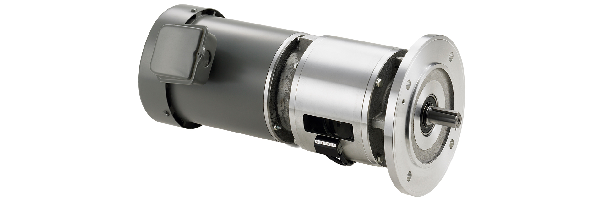
This model features a standard three-phase motor directly connected to the input shaft of the 125-series electromagnetic clutch/brake unit, allowing the output shaft to be repeatedly started and stopped without stopping the motor. It enables high-frequency intermittent operation compared to simply turning the motor on and off. It is designed for flange mounting.
[Specifications]
| Model | Size | Dynamic friction torque Td [N·m] | Static friction torque Ts [N·m] | Coil (at 20°C) | Heat Resistance Class | Motor Output [kW] | Rotating mass moment of inertia J [kg·m²] | Total work until air gap readjustment ET [J] | Armature pull-in time ta [s] | Torque rise time tp [s] | Torque decay time td [s] | Mass [kg] | |||
|---|---|---|---|---|---|---|---|---|---|---|---|---|---|---|---|
| Voltage [V] | Power [W] | Current [A] | Resistance [Ω] | ||||||||||||
| 126-06-4F 0.2 kW | 06 | 5 | 5.5 | DC24 | 11 | 0.46 | 52 | B | 0.2 | 1.28×10⁻⁴ | 36×10⁶ | C: 0.020 / B: 0.015 | C: 0.041 / B: 0.033 | C: 0.020 / B: 0.015 | 8.9 |
| 126-08-4F 0.4 kW | 08 | 10 | 11 | DC24 | 15 | 0.63 | 38 | B | 0.4 | 3.70×10⁻⁴ | 60×10⁶ | C: 0.023 / B: 0.016 | C: 0.051 / B: 0.042 | C: 0.030 / B: 0.025 | 13 |
| 126-10-4F 0.75 kW | 10 | 20 | 22 | DC24 | 20 | 0.83 | 29 | B | 0.75 | 1.40×10⁻³ | 130×10⁶ | C: 0.025 / B: 0.018 | C: 0.063 / B: 0.056 | C:0.050 / B:0.030 | 18 |
| 126-12-4F 1.5 kW | 12 | 40 | 45 | DC24 | 25 | 1.09 | 23 | B | 1.5 | 3.85×10⁻³ | 250×10⁶ | C: 0.040 / B: 0.027 | C: 0.115 / B: 0.090 | C: 0.065 / B: 0.050 | 36 |
| 126-16-4F 2.2 kW | 16 | 80 | 90 | DC24 | 35 | 1.46 | 16 | B | 2.2 | 1.35×10⁻² | 470×10⁶ | C: 0.050 / B: 0.035 | C: 0.160 / B: 0.127 | C:0.085 / B:0.055 | 42.5 |
| 126-16-4F 3.7 kW | 16 | 80 | 90 | DC 24 | 35 | 1.46 | 16 | B | 3.7 | 1.35×10⁻² | 470×10⁶ | C: 0.050 / B: 0.035 | C: 0.160 / B: 0.127 | C: 0.085 / B: 0.055 | 57 |
- The 0.2 kW and 0.4 kW motors are totally enclosed, externally ventilated motors that comply with JIS C 4210, while motors rated at 0.75 kW or higher comply with JIS C 4213.
- The motor's input power supply is 200 V AC / 50 Hz, or 200 V AC or 220 V AC / 60 Hz.
- If you require special voltages (5-power-supply specifications) or different pole counts for general-purpose motors, please contact us.
- The dynamic friction torque Td is the value at a relative speed of 100 min⁻¹. Additionally, depending on the initial torque characteristics, a break-in period may be required.
[Dimensions]
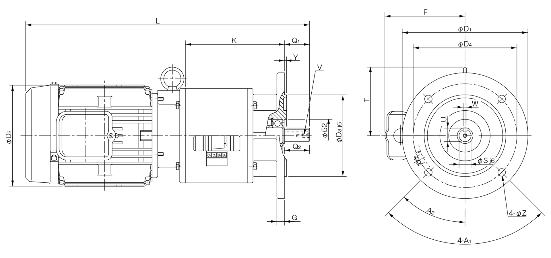
Unit [mm]
| Model | Unit Dimensions | Shaft Dimensions | |||||||||||||||||
|---|---|---|---|---|---|---|---|---|---|---|---|---|---|---|---|---|---|---|---|
| A1 | A2 | D1 | D2 | D3 | D4 | F | G | K | L | T | Y | Z | Q1 | Q2 | S | U | V | W | |
| 126-06-4F-N 0.2 kW | 90° | 45° | 160 | 130 | 110 | 130 | - | 8 | 107 | 335 | - | 3.5 | 10 | 23 | 25 | 11 | 12.5 | M4×0.7, depth 8 | 4 |
| 126-08-4F-N 0.4 kW | 90° | 45° | 160 | 145 | 110 | 130 | 124 | 10 | 130.5 | 389 | - | 3.5 | 10 | 30 | 30 | 14 | 16 | M4×0.7, depth 8 | 5 |
| 126-10-4F-N 0.75 kW | 90° | 45° | 200 | 163 | 130 | 165 | 131 | 12 | 157.5 | 463 | - | 3.5 | 12 | 40 | 40 | 19 | 21.5 | M6×1, depth 11 | 6 |
| 126-12-4F-N 1.5 kW | 90° | 45° | 200 | 180 | 130 | 165 | 145 | 12 | 197.5 | 551 | 133 | 3.5 | 12 | 50 | 50 | 24 | 27 | M6×1, depth 11 | 8 |
| 126-16-4F-N 2.2 kW | 90° | 45° | 250 | 199 | 180 | 215 | 153 | 16 | 260.5 | 660 | 161 | 4 | 15 | 60 | 60 | 28 | 31 | M6×1, depth 11 | 8 |
| 126-16-4F-N 3.7 kW | 90° | 45° | 250 | 223 | 180 | 215 | 166.5 | 16 | 260.5 | 681.5 | 161 | 4 | 15 | 60 | 60 | 28 | 31 | M6×1, depth 11 | 8 |
- *Flange and output shaft dimensions comply with IEC and JEM standards for flange motors. (Size 06 includes a key and keyway.)
- *When installing pulleys or similar components on the output shaft, please use the included installation kit.