121 (10G) Type (Dual Clutch)
![三木プーリのダブルクラッチユニット 121[10G]タイプ 製品画像(電磁ダブルクラッチ構成・動力切替制御・産業用駆動機器)](/media/cb_uk_0cc_121_0l.jpg)
This double-clutch unit features the same through-shaft design as the Type 121 (20) electromagnetic clutch and brake unit, with electromagnetic clutches mounted on both sides of the drum. It can be used with the hub as the input for two-speed transmission or forward/reverse operation, or with the shaft as the input for power distribution and other applications.
[Specifications]
| Model | Size | Dynamic friction torque Td [N·m] | Static friction torque Ts [N·m] | Coil (at 20°C) | Temperature Class | Maximum rotational speed [min⁻¹] | Rotating mass moment of inertia J [kg·m²] | Total work until air gap readjustment ET [J] | Armature attraction time ta [s] | Torque rise time tp [s] | Torque decay time td [s] | Mass [kg] | ||||
|---|---|---|---|---|---|---|---|---|---|---|---|---|---|---|---|---|
| Voltage [V] | Power [W] | Current [A] | Resistance [Ω] | When hub input | Shaft input | |||||||||||
| 121-06-10G | 06 | 5 | 5.5 | DC24 | 11 | 0.46 | 52 | B | 3000 | 1.55×10⁻⁴ | 1.05×10⁻⁴ | 36×10⁶ | C: 0.020 / B: 0.015 | C: 0.041 / B: 0.033 | C:0.020 / B:0.015 | 1.7 |
| 121-08-10G | 08 | 10 | 11 | DC24 | 15 | 0.63 | 38 | B | 3000 | 4.75×10⁻⁴ | 3.00×10⁻⁴ | 60×10⁶ | C: 0.023 / B: 0.016 | C:0.051 / B:0.042 | C:0.030 / B:0.025 | 3.1 |
| 121-10-10G | 10 | 20 | 22 | DC24 | 20 | 0.83 | 29 | B | 3000 | 1.44×10⁻³ | 9.45×10⁻⁴ | 130×10⁶ | C: 0.025 / B: 0.018 | C: 0.063 / B: 0.056 | C:0.050 / B:0.030 | 6.5 |
| 121-12-10G | 12 | 40 | 45 | DC24 | 25 | 1.04 | 23 | B | 3000 | 4.50×10⁻³ | 2.75×10⁻³ | 250×10⁶ | C: 0.040 / B: 0.027 | C:0.115 / B:0.090 | C:0.065 / B:0.050 | 10.5 |
| 121-16-10G | 16 | 80 | 90 | DC24 | 35 | 1.46 | 16 | B | 3000 | 1.34×10⁻² | 9.05×10⁻³ | 470×10⁶ | C: 0.050 / B: 0.035 | C:0.160 / B:0.127 | C:0.085 / B:0.055 | 21 |
| 121-20-10G | 20 | 160 | 175 | DC24 | 45 | 1.88 | 13 | B | 2500 | 4.18×10⁻² | 2.65×10⁻² | 10×10⁸ | C: 0.090 / B: 0.065 | C:0.250 / B:0.200 | C:0.130 / B:0.070 | 38.5 |
| 121-25-10G | 25 | 320 | 350 | DC24 | 60 | 2.50 | 9.6 | B | 2000 | 9.80×10⁻² | 7.45×10⁻² | 20×10⁸ | C: 0.115 / B: 0.085 | C:0.335 / B:0.275 | C:0.210 / B:0.125 | 70 |
- The dynamic friction torque Td is the value at a relative speed of 100 min⁻¹. Additionally, depending on the initial torque characteristics, a break-in period may be required.
- The moment of inertia of the rotating assembly during shaft input is equal to the value for a single Type 5 armature.
[Dimensions]
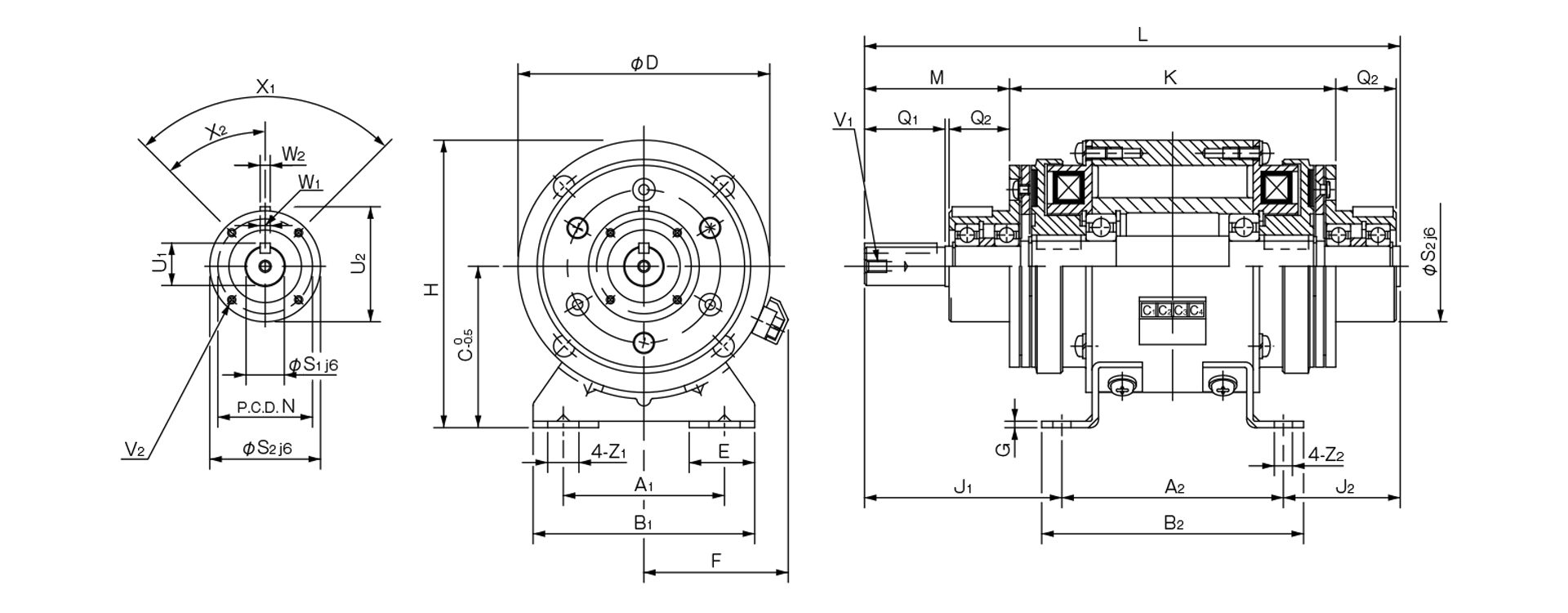
| Size | Unit Dimensions | |||||||||||||||||
|---|---|---|---|---|---|---|---|---|---|---|---|---|---|---|---|---|---|---|
| A1 | A2 | B1 | B2 | C | D | E | F | G | H | J1 | J2 | K | L | M | N | Z1 | Z2 | |
| 06 | 52.5 | 75 | 80 | 90 | 55 | 80 | 27.5 | 53 | 2.6 | 95 | 65.5 | 40.5 | 111.5 | 181 | 47 | 33 | 13.5 | 6.5 |
| 08 | 65 | 90 | 90 | 105 | 65 | 100 | 27.5 | 61 | 2.6 | 115 | 78.5 | 48.5 | 133 | 217 | 57 | 37 | 13.5 | 6.5 |
| 10 | 80 | 110 | 110 | 130 | 80 | 125 | 32.5 | 72 | 3.2 | 142.5 | 98 | 58 | 162 | 266 | 72 | 47 | 15.5 | 9 |
| 12 | 105 | 135 | 140 | 160 | 90 | 150 | 35 | 81 | 3.2 | 165 | 121 | 71 | 193 | 327 | 92 | 52 | 20 | 11.5 |
| 16 | 135 | 160 | 175 | 185 | 112 | 190 | 42.5 | 97 | 4.5 | 207 | 149 | 87.5 | 232 | 397 | 113 | 62 | 24.5 | 11.5 |
| 20 | 155 | 200 | 200 | 230 | 132 | 230 | 45 | 109 | 6 | 247 | 187 | 105 | 290 | 492 | 142 | 74.5 | 28 | 14 |
| 25 | 195 | 240 | 240 | 270 | 160 | 290 | 47.5 | 124 | 20 | 305 | 238 | 125 | 350 | 603 | 183 | 101.5 | 28 | 14 |
| Size | Shaft Dimensions | CAD File No. | ||||||||||
|---|---|---|---|---|---|---|---|---|---|---|---|---|
| Q1 | Q2 | S1 | S2 | U1 | U2 | V1 | V2 | X1 | X2 | W1,2 | ||
| 06 | 25 | 20 | 11 | 38 | 12.5 | 39.5 | M4×0.7, depth 8 | 3-M4×0.7 depth 4 | 3-120° | 60° | 4 | 121-101 |
| 08 | 30 | 25 | 14 | 45 | 16 | 47 | M4×0.7, depth 8 | 3-M4×0.7 depth 6 | 3-120° | 60° | 5 | 121-102 |
| 10 | 40 | 30 | 19 | 55 | 21 | 57 | M6×1, depth 11 | 4-M4×0.7, depth 8 | 4-90° | 45° | 5 | 121-103 |
| 12 | 50 | 40 | 24 | 64 | 27 | 67 | M6×1, depth 11 | 4-M4×0.7 depth 8 | 4-90° | 45° | 7 | 121-104 |
| 16 | 60 | 50 | 28 | 75 | 31 | 78 | M6×1, depth 11 | 6-M5×0.8 depth 8 | 6-60° | 30° | 7 | 121-105 |
| 20 | 80 | 60 | 38 | 90 | 41.5 | 93.5 | M10×1.5, depth 17 | 4-M6×1, depth 12 | 4-90° | 45° | 10 | 12 1-106 |
| 25 | 110 | 70 | 42 | 115 | 45.5 | 118.5 | M10×1.5, depth 17 | 8-M6×1, depth 12 | 8-45° | 22.5° | 12 | 121-107 |
- The input/output keyways comply with the old JIS Type 2 standard, while the keys comply with the old JIS Type 1 standard. Please note that the dimensions of the keyways on the unit hub do not conform to JIS standards. Please refer to the dimension table above.
- When inserting pulleys or similar components into the input or output, please use the included insertion set.
- The base of the 121-25-10G is made of cast metal.