Coupling Q&A;
2026/05/07
All Your Questions About Couplings Answered!
This page provides technical terms and answers to common technical questions regarding couplings. For
other frequently asked questions, please click here. If you cannot find
the answer to your question, please contact us using the "Contact Form."
Table of Contents
Q. Please tell me about the different types of couplings.
A. Couplings, which connect shafts to transmit power, are classified based on the relative positions of the two shafts, the method of absorbing mounting errors (eccentricity, angular misalignment, and axial displacement), and the presence or type of flexible material.
Rigid couplings: These cannot accommodate mounting errors but are inexpensive. They generate high reaction forces and are suitable for low-speed rotation. Flexible
couplings: These can accommodate mounting errors between shaft centers.
Flexible couplings include types such as gear, chain, metal spring, and rubber. Our company primarily handles flexible shaft couplings.
Additionally, the type of coupling must be selected based on the application. For example, when the drive source is an engine, rubber or plastic couplings with good vibration absorption properties are used, whereas metal couplings with high torsional rigidity are used for precision machinery such as servo motors.
→ For more detailed information on types, please see "Types and Features of Couplings."
Q. Please tell me about installation tolerances.
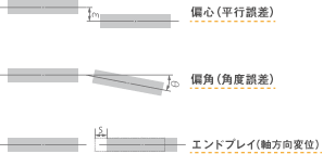
A. Misalignment in couplings can be divided into three categories:
(1) Eccentricity: This occurs when the centers of the shafts do not align, resulting in a misalignment of the centerlines. (2) Angular misalignment: This occurs when the centerlines of the shafts are offset at an angle (i.e., bent).
(3) Axial displacement: This occurs when the centerlines of the shafts align, but there is movement in the axial direction.
Q. What is resonance?
A. When an external force causes a vibration at the same frequency as an object’s natural frequency, the object vibrates even more strongly than the applied vibration. This phenomenon is called resonance.
In other words, it occurs when the natural frequency matches the excitation frequency. In the case of coupling resonance, since the vibration occurs in the rotational direction, it is referred to as torsional resonance.
(Since motors have minimal rotational irregularities and generate little torsional vibration, resonance is rarely a problem. However, resonance occasionally occurs in stepper motors.)
The natural frequency is an inherent property of the object and does not change; however, the excitation frequency varies in proportion to engine speed.
Therefore, resonance occurs at a specific rotational speed where the natural frequency and the excitation frequency coincide. Consequently, knowing the
natural frequency of the object is important; our engine couplings include a simple calculation formula for determining the natural frequency in the catalog.
Incidentally, the natural frequency of the human body is said to be 2–3 Hz.
In a resonance state, the amplitude of vibration (the extent of oscillation) is amplified, becoming much larger than would normally be expected. Have you ever experienced driving
on a highway in a car with unbalanced tires, where the vibration becomes stronger at a certain speed but decreases once you exceed that speed? The point where the vibration becomes strongest is the resonance point, and the speed at that moment is the resonance speed, or resonance RPM.

Q. Please explain the torsional spring constant.
A. First, let’s consider the spring constant of a coil spring. When a coil spring is suspended from the ceiling with no weight attached and hanging freely, its length is denoted as A:m. If we then attach a weight of W:N, the coil spring extends to a length of B:m.
The spring constant is a measure of how much the spring extends when a certain load is applied.
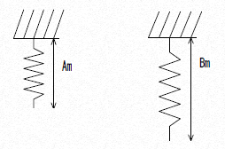
Spring constant = W N ÷ (B:m – A:m)
This is expressed by the formula above, and the unit is N/m. The torsional
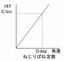
spring constant is the equivalent of the linear spring constant, but applied in the rotational direction. The torsional spring constant describes the relationship between the force applied to twist an object in a rotational direction and the resulting angle of twist.
For example, if a torque of C Nm is applied to a coupling and the coupling twists by D deg in response to that force, the torsional spring constant is expressed
as Torsional Spring Constant = C Nm / D deg, with the
unit being Nm/deg.
Our catalog lists several units for torsional spring constants. Generally, the unit Nm/rad is used for torsional spring constants
. Rad (radians) is a unit of angle, where 1 rad = 180/π deg = 57.3 deg.
In couplings, those that are flexible in the rotational direction, such as rubber couplings, generally have a low torsional spring constant, while those that are rigid in the rotational direction, such as metal plate spring couplings, have a high torsional spring constant.
Q. Please explain the concept of moment of inertia.
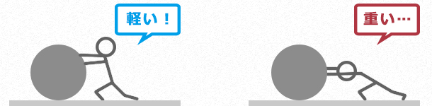
A. For example, consider rolling a ping-pong ball and an iron ball of the
same size to a certain speed. The ping-pong ball starts rolling with a light force, but moving the iron ball requires more force than the ping-pong ball.
Conversely, when a ping-pong ball and an iron ball are rolling at the same speed, the iron ball requires far more time and distance to come to a natural stop. If you try to stop them forcefully, the iron ball requires more force. In this
way, the ease with which an object can be moved to a certain speed, and the amount of force remaining when trying to stop an object from that speed, is referred to as inertia.
Moment of inertia is the inertia that arises when an object rotates; it is an important unit for understanding how easily an object rotates, how easily it stops, and how force is applied during rotation. The formula for calculating moment of inertia varies depending on the shape of the rotating object relative to its center of rotation. It is expressed
in the unit "kg·m²."
Why is it necessary to know the moment of inertia? For example, our SFS (sheet metal spring coupling) improves positioning accuracy when used with servo motors. However, if the moment of inertia is too large, the response during startup and stopping becomes sluggish, which affects positioning accuracy.
→ For the calculation formula for moment of inertia, please refer to the "List of Moment of Inertia J Calculation Formulas."
→ If you wish to know the moment of inertia, please refer to the "Moment of Inertia J Quick Reference Table."
Q. What are continuous torque, maximum torque, and allowable torque?
We use two different approaches. One involves determining a standard torque (rated torque) and setting the maximum torque to approximately twice that value, assuming the maximum torque will be applied only a few dozen times per day. The other
approach involves determining the maximum allowable torque—similar to that of a metal plate spring coupling—and assuming the torque will remain below that limit.
We select the appropriate method based on the coupling’s structure and type. Generally, metal disc spring couplings specify an “allowable torque.” Metal disc spring
couplings are frequently used with servo motors, which generate a maximum torque of approximately three times or more the continuous torque.
Additionally, since there are frequent starts and stops, the coupling must be capable of withstanding these maximum torque levels. Therefore
, it is sufficient to select a coupling based on its allowable torque.
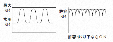
On the other hand, general-purpose motors and engines are typically operated at their rated torque, with maximum torque occurring only during start-up and stop cycles, which occur about several dozen
times a day. Based on this usage, the transmission torque of the coupling is expressed in terms of rated torque and maximum torque.
In either case, the coupling must not be operated beyond its maximum torque or rated torque.
Q. Please tell me about balance.
In JIS standards, balance is defined as “balance quality.” (→ Click here for detailed information on balance quality)
① The balance of a rotating body refers to the imbalance in mass distribution that occurs when the rotating body (such as a coupling) rotates. For example, if you attach a weight to the end of a spinning top and spin it, an imbalance equal to the mass of that weight occurs in the top.
Conversely, this imbalance in mass is called the imbalance amount and is ultimately expressed in terms of mass.
② When the amount of imbalance is large, it is generally said that the balance is poor; rotating the component in this state causes vibration.
Furthermore, the magnitude of this vibration varies depending on the amount of imbalance and the rotational speed. Increasing the rotational speed when the amount of imbalance is large results in greater vibration. Conversely
, when the amount of imbalance is small and the rotational speed is low, the vibration is reduced.
③ The process of correcting and reducing the imbalance in a rotating body is generally referred to as “balancing” and is termed “tsuriawase” in JIS standards. There
are two types of balancing: single-plane balancing, which corrects the imbalance at one point on the rotating body, and two-plane balancing, which corrects it at two points.
④ In JIS standards, balancing specifications are denoted as G□□ and referred to as “balance grades.”
For example, G6.3, G100, and G4000—the numbers following the “G” vary in range. These
numbers represent the grade; the smaller the number, the better the balance, and the higher the balance grade. The
higher the grade, the more suitable the rotating component is for use in precision machinery.The couplings we handle are balanced to grades ranging from G2.5 to G16.
⑤ Balancing is performed by removing the mass equivalent to the amount of imbalance. The mass of the imbalance required to meet the specified balance grade is determined through calculation.As the
balance grade increases, the mass of the unbalanced portion to be removed decreases, so balancing takes longer.
Additionally, if a coupling corrected on a balancing machine is removed and then reinstalled before measurement, the unbalanced mass may differ. This also depends on the coupling’s installation
and alignment accuracy. This is referred to as balance repeatability.

Q. What is the operating temperature range for the coupling?
The operating temperature range varies depending on the coupling’s material and specifications. For example
, the natural rubber used in our rubber couplings vitrifies at low temperatures of -40°C, and at high temperatures of 120°C, the surface hardens, making it prone to wrinkling and cracking. For this reason, the operating temperature range for rubber couplings is set between -30°C and 95°C.
Similarly, couplings made of aluminum or stainless steel may undergo thermal expansion at high temperatures; therefore, for safety reasons, we limit their maximum operating temperature to 120°C. While it may be possible to use them outside this operating temperature range under certain conditions
, doing so may result in a shorter service life or failure to meet the original specifications.
→ For detailed operating temperature information for each coupling, please download the catalog from the respective product page or request a catalog via the "Request a Free Catalog" link.
Q. Does installation misalignment reduce the transmission efficiency of the coupling?
Yes. In the case of elastic
couplings, mounting misalignment is absorbed by the deformation of the flexible material (rubber, plastic, or metal); however, this deformation generates a reaction force on the bearings and other components. In other words
, the power generated by the motor is slightly reduced due to the reaction force exerted on the bearings by the coupling.
Consequently, since some power is lost, transmission efficiency decreases. As described above
, in terms of transmission efficiency, the smaller the installation error, the better the transmission efficiency; similarly, the smaller the reaction force on the bearings caused by installation errors, the better the transmission efficiency.
Q. What is the angular velocity change of a coupling?
Angular velocity variation refers to the slight irregularities in the rotational speed of the driven side that occur via a coupling, even though the driving side is rotating at a constant speed. In typical couplings, if there is a certain degree of installation error,
angular velocity variation will occur to some extent on the driven side. However
, with an angular misalignment of 1° or less, the angular velocity variation rate is approximately 1%, which is generally not a significant issue.
(This does not apply to special equipment that requires constant-speed operation.)
Q. How can I minimize changes in angular velocity?
By minimizing the eccentricity and angular misalignment, angular velocity variations can be suppressed. In
particular, the double-element model of the Servoflex coupling exhibits minimal angular velocity variation due to mounting errors, making it ideal for use with angle sensors. If constant-speed performance
is required despite significant mounting errors, we recommend using a constant-speed joint or similar device.
Q. Are there any couplings with high electrical insulation properties?
Generally speaking, rubber and resin couplings provide insulation.
However, there are varying levels of insulation, so it cannot be assumed that they are inherently insulating. Depending
on the material and shape, some rubber and resin couplings may have low insulation resistance, so verification is necessary.
For example, our CF-X (resin coupling) has an insulation resistance of ∞Ω, whereas the CF-A (rubber coupling) has an insulation resistance of 0.04 to 0.3 × 10^6Ω.Generally, insulation is considered to exist at 10^14 Ω.
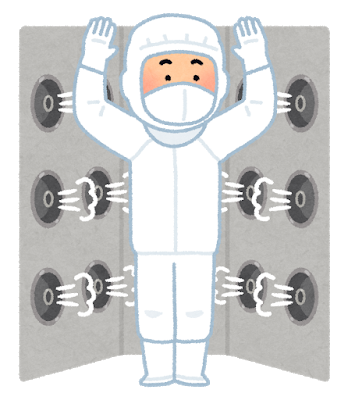
Q. Are there any couplings that can be used in a cleanroom?
Generally, the requirements for use in cleanrooms include that materials must not generate fine dust, oil, or rust due to friction.
However, depending on the specific cleanroom conditions, a certain level of fine dust may be permissible. Since transmission-related
equipment, such as couplings, consists of multiple components, there are inevitably parts that experience friction and parts that are subjected to stress.
Furthermore, while aluminum and stainless steel are resistant to surface rust and corrosion, materials made of standard iron without surface treatment will rust, and fine wear particles and rust dust will inevitably be generated from these areas. Although the severity may vary
, assuming conditions similar to those of other machinery used in cleanrooms, we recommend couplings made of stainless steel or those with special surface treatments. Please contact us for more details
.
Q. What is the difference between the minimum hole diameter and a pilot hole?
The minimum hole diameter refers to the diameter of a hole that has undergone finishing operations. Therefore, it represents the smallest diameter that can be used as-is. A pilot hole, on
the other hand, is a hole that has been drilled to center the workpiece as a preliminary step before finishing the hole
. Pilot holes are generally created because they make it easier to finish the hole.
Q. How do you determine the maximum RPM?
One factor is determined by material strength. The permissible peripheral speed is calculated based on the material strength of the coupling’s weakest section
, and the maximum rotational speed is determined based on the coupling material’s diameter and the permissible peripheral speed.
Another factor is balance. Generally, the maximum rotational speed does not take balance into account.
Therefore, when used at high speeds, balance must be considered separately, and in some cases, the maximum rotational speed is set based on these limits.
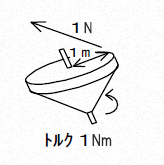
Q. What is torque? (What does the unit mean?)
In physics, this is expressed as a moment. Torque is the force that causes a rotating object to turn, and it is calculated as the product of the force and the distance from the center of rotation. For example, if you
try to spin a top with a radius of 1 m using a force of 1 N in the direction tangent to the top’s outer circumference, the
torque is “1 m × 1 N = 1 Nm.” The unit of
torque is Nm.
Q. What happens if I don’t tighten the bolts to the specified torque?
If the tightening torque of a bolt does not meet the specified torque, the bolt will not be able to perform its intended function. There is also a risk that the bolt will loosen. As a result, shear forces will act on the bolt, ultimately leading to bolt failure.
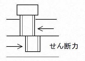
Conversely, if a bolt is tightened beyond the specified torque, excessive stress is applied to the bolt, potentially leading to failure. Alternatively, the material at the bolt seat may buckle, reducing the axial force and causing the bolt to fail.
As described above, if bolts are not tightened to the specified torque, the coupling may not perform as intended, and in the worst case, the product may be damaged.
Q. What happens if the product is used beyond the specifications listed in the catalog?
Examples include excessive mounting misalignment, excessive torque, excessive torque fluctuations, and operation outside the specified ambient temperature range. Under
such conditions, the coupling may not be able to perform as intended.
Typically, this results in a shorter coupling lifespan. In the worst-case scenario, the product may even be damaged.
Q. What are the different methods for connecting a coupling to a shaft?
There are several ways to connect a coupling to a shaft.
| Types | Photo | Features |
|---|---|---|
| Key Connection | 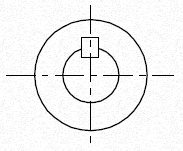 | This is a key-based connection in which keyways are machined into both the coupling bore and the shaft, and torque is transmitted by inserting a key. In this case, tightening with set screws presses the shaft against the side of the coupling bore, improving torque transmission efficiency. With key connections , gaps form between the keyway and the key, as well as between the bore and the shaft; depending on the load, play can occur through these gaps, resulting in backlash. |
| Set Screw Fastening | 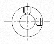 | This method connects the bore and shaft solely by tightening set screws, without using keys. The axial force of the set screws affects the magnitude of the transmitted torque. Generally, set screw connections do not provide sufficient torque, so the shaft is designed with a flat section to increase the transmitted torque. This method is used for couplings with low torque requirements or small bore diameters (up to approximately φ20). |
| Single-clamp fastening | 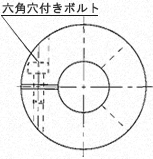 | ・Suitable for servo applications with forward and reverse rotation. ・Easy to install . Shaft diameters are typically 35 mm or less. |
| Double-clamp fastening | 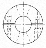 | ・Higher shaft holding force than single clamps. ・Easy to align the shaft center, allowing for fine adjustment (integrated type); high precision. ・Shaft diameters up to approximately 40 mm |
| Taper Clamping | 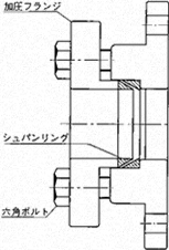 | ・Higher shaft holding force than double clamps. ・Requires a large number of tightening bolts and axial space. ・Supports high speeds of 20,000 rpm or more . |
Q. What is the difference between backlash and torsional lag?
Backlash refers to the mechanical play inherent in a coupling. When mechanical components are assembled, rotational play can occur due to the fit between keys and shafts or gaps between parts. This is called backlash
. For example, it refers to the range of angles where torque is not transmitted when switching from forward to reverse rotation. Backlash is unsuitable for couplings used in applications such as servo motors, which require high rotational and positioning accuracy.
Torsional lag is strictly distinct from backlash. Torsional
lag is particularly noticeable in couplings with low torsional rigidity.
For example, in rubber couplings, the rubber is compressed in the rotational direction from the moment torque is applied until it reaches a state where torque can be transmitted. The drive side begins to rotate, the rubber is compressed until it can transmit torque, and only then does the driven side begin to rotate.The period from the
initial state when the driving side begins to rotate until the driven side begins to rotate is called torsional lag. Whether it is
backlash or torsional lag, these couplings cannot be used in applications that require positioning accuracy. However
, because torsional lag absorbs fluctuating torque and vibrations during rotation due to its inherent characteristics, it is used in couplings for engines and other applications where positioning accuracy is not a concern.
Q. What are the machining tolerances for keys?
JIS standards specify fit tolerances for holes and shafts, keys and keyways, and other similar combinations.
(→ List of Fit Tolerances)
A fit refers to the relationship resulting from the dimensional difference between a hole and a shaft prior to assembly. Fits
are classified into grades, which are denoted by the symbol "IT" followed by a number indicating the grade. The clearance of
the fit is determined by this grade.
Broadly speaking, fits are classified into loose fits, intermediate fits, and tight fits. Since intermediate
and tight fits require press-fitting or hammering during assembly, we recommend using a loose fit for Miki Pulley couplings.
In the case of parallel keys, which we commonly use, current JIS (New JIS) standards specify key dimensions and define two types of keyway dimensions corresponding to them. These
tolerances are P9 (Precision Grade) and Js9 (Standard Grade).
However, Miki Pulley’s standard bore machining specification uses H9 grade. We do not recommend P9 or Js9 grades because both result in interference or close-fit key-way assemblies.
H9 grade allows for easy assembly with a clearance fit and poses no performance issues.
The JIS standard for keys was revised in 1976. Standards prior to this revision are referred to as the "Old JIS Standard," while those after are called the "New JIS Standard" to distinguish them. The Old
JIS Standard has two types (Type 1 and Type 2), and Miki Pulley’s standard bore machining specifications adopt Type 2, which has a larger tolerance. The
keyway width for this is Grade E9. Since this is a clearance fit, there are no issues with its use.
In addition to the New JIS and Old JIS standards, there is a separate standard for "New Standard Motor Compatibility.
" This refers to
motors manufactured to new standards, where the key dimensions differ slightly from those of the JIS standard. Since the key width relative to the bore diameter and tolerances differ among the New JIS, Old JIS, and New Standard Motor Compatibility standards, it is essential to verify them to avoid confusion.
→ Miki Pulley Coupling Standard Bore Machining Specifications
Q. What happens if the coupling is used beyond its maximum installation tolerance?
Results may vary depending on the type of coupling and the components involved, but generally, since a safety factor is applied, the coupling will not fail immediately—though this does depend on the magnitude of the installation error. However, its service life will be shortened, and component parts may eventually fail; since these are rotating parts, they could fly off, posing a serious hazard. Therefore, the coupling must not be used with installation errors exceeding the maximum allowable limit.
Our skilled technicians will select the right coupling for your equipment!
Are you experiencing any issues with your equipment?
At Miki Pulley, we can select and customize the perfect coupling for your specific equipment from our wide range of options! Feel free to contact
us using the form below!