Miki Pulley Standard Bore Specifications for Couplings
2026/05/07
This standard drilling specification applies to Servoflex (excluding SFC), Spaflex, Baumannflex (excluding ZG and LM), and Centaflex models for holes ranging from 6 mm to 65 mm. However, if a specific drilling specification has been established for a particular model, that specification takes precedence and may differ from this standard.
Hole machining tolerances relative to mating part tolerances
Unless otherwise specified, we will machine to H7. However, for diameters of 10 mm or less, we will machine to H8. The table below shows the recommended bore tolerances relative to shaft tolerances. Tolerances other than H7 require separate consultation. Please note that when reaming a pre-drilled hole, the surface treatment on the reamed section will be removed. If surface treatment is required after reaming, please contact us separately.
| Shaft Tolerance | Recommended Bore Tolerances |
|---|---|
| h6–h9 | H7 |
| j6 | G7 |
| k6 | F7 |
| m6 | F7 |
*j6, k6, and m6 are used in the new standard motor shafts.
Keyway dimensions relative to hole diameter (see table below)
Unless otherwise specified, we will machine the parts in accordance with the old JIS (Type 2) standard. Keyways will not be machined into holes smaller than 12 mm.
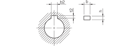
Compliant with the former JIS standard (Type 2)
Unit [mm]
| Hole diameter | b2 | t2 | Key dimensions b×h | |||
|---|---|---|---|---|---|---|
| Reference dimension | Tolerance (E9) | Reference dimension | Tolerance | |||
| 12 or more, 13 or less | 4 | +0.050 +0.020 | 1.5 | +0.3 0 | 4×4 | |
| Greater than 13 and less than or equal to 20 | 5 | 2.0 | 5×5 | |||
| Over 20 and 30 or less | 7 | +0.061 +0.025 | 3.0 | +0.3 0 | 7×7 | |
| Over 30 and 40 or less | 10 | 3.5 | 10×8 | |||
| Over 40 and 50 or less | 12 | +0.075 +0.032 | 12×8 | |||
| Over 50 and 60 or less | 15 | 5.0 | 15×10 | |||
| Over 60 and 65 or less | 18 | 6.0 | 18×12 | |||
Compliant with JIS standards
Unit [mm]
| Hole diameter | b2 | t2 | Key dimensions b×h | ||
|---|---|---|---|---|---|
| Reference dimension | Tolerance (H9) | Reference dimension | Tolerance | ||
| 12 | 4 | +0.030 0 | 1.8 | +0.3 0 | 4×4 |
| Greater than 12 and less than or equal to 17 | 5 | 2.3 | 5×5 | ||
| Greater than 17 and less than or equal to 22 | 6 | 2.8 | 6×6 | ||
| Greater than 22 and less than or equal to 30 | 8 | +0.036 0 | 3.3 | +0.3 0 | 8×7 |
| Over 30 and 38 or less | 10 | 10×8 | |||
| Over 38 and 44 or less | 12 | +0.043 0 | 12×8 | ||
| Over 44 and 50 or less | 14 | 3.8 | 14×9 | ||
| Over 50 and 58 or less | 16 | 4.3 | 16×10 | ||
| Over 58 and 65 or less | 18 | 4.4 | 18×11 | ||
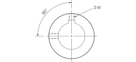
Nominal diameter of set screws for keyways
| Keyway reference dimension b2 | Set screw nominal diameter |
|---|---|
| 4 | M4 |
| 5 | M4 |
| 6 | M5 |
| 7 | M6 |
| 8 | M6 |
| 10 | M8 |
| 12 | M8 |
| 14 | M10 |
| 15 | M10 |
| 16 | M10 |
| 18 | M10 |
*Unless otherwise specified, the set screws will be positioned at two 90° angles.
*Note: The position of the set screws varies depending on the product; please refer to the standard hole specifications for each product for details.
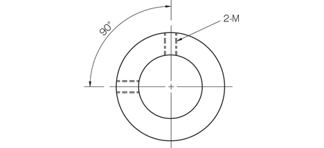
Nominal diameter of set screw relative to hole diameter (when there is no keyway)
| Hole diameter | Set screw nominal diameter |
|---|---|
| 6 or more but less than 12 | M4 |
*Unless otherwise specified, the set screws will be positioned at two 90° angles.
*Note: The position of the set screws varies depending on the product; please refer to the standard hole specifications for each product for details.
Other Technical Documents
↓You can download the following technical documents as a single PDF file.
Specifications
Hole Machining, Tolerances, and Fits
Calculations, Conversions, Formulas, and Units
Machine Elements
- Hexagon Socket Head Cap Screw Standards List | Excerpt from JIS B 1176
- Shapes and Dimensions of Hexagon Socket Set Screws (Excerpt from JIS B 1177-1997)
- Shapes and Dimensions of Hex Bolts (Component Grade A) (Excerpt from JIS B 1180-1985)
- How to Use Hex Socket Set Screws
- Mechanical Properties of Steel Bolts and Screws (Excerpt from JIS B 1051-2000)
- Shapes and Dimensions of Hexagonal Wrenches (Hex Wrenches/L-Wrenches/Hex Wrenches) (Excerpt from JIS B 4648:2008)
- List of Standards for Dimensions and Tolerances of Parallel Keys and Keyways (Excerpt from JIS B 1301-1996/JIS B 1301-1959 [Old JIS])
- Snap Rings (C-Type Retaining Rings/C-Rings) Standards and Dimensions List (Excerpt from JIS B 2804-2010)
- Shim Dimensions
- Ball Bearing Standard Dimensions Table - JIS Excerpt
Material Properties
Terminology
- Glossary of Electromagnetic Clutch and Electromagnetic Brake Terms (Excerpt from JIS B 1404-1:2005)
- Glossary of Screw Terms (JIS B 0101:2013)
- Glossary of Fit Tolerances (Excerpt from JIS B 0401-1:2016)
- Glossary of Terms for Chains, Sprockets, and Accessories (Excerpt from JIS B 1812:2015)
- Glossary of Friction Belt Transmission Terms (Excerpt from JIS B 1860:2018)
- Technical Drawing—Terminology (Excerpt from JIS Z 8114:1999)