Dimensions and Tolerances for Parallel Keys and Keyways: List of Standards (Excerpt from JIS B 1301-1996/JIS B 1301-1959 [Old JIS])
2026/05/07
You can download the content of this page as a PDF
[Scope]
This standard specifies steel parallel keys, tapered keys, and half-moon keys used in general machinery, as well as the corresponding keyways.
*This page provides an excerpt regarding parallel keys.
[Reference Information]
1. Parallel keys are available in two types: "without threaded holes" and "with threaded holes."
2. The ends of parallel keys come in three types: "both ends rounded," "both ends square," and "one end rounded." Unless otherwise specified, the standard type is "both ends square."
3. The entries “Clamp Type” and “Standard Type” in the table indicate the form of the connection between the key and the shaft/hub. The clamp
type refers to a connection where the hub is clamped onto a key fixed to the shaft, or where a key is driven between an assembled shaft and hub.
The standard type refers to a connection where the hub is fitted onto a key fixed to the shaft.
4. Parallel keys are designated by their standard number, type, and nominal dimensions × length.
Example: JIS B 1301 Parallel Key without Hole for Screws, Both Ends Rounded, 25×14×90
JIS Standard (Excerpt from JIS B 1301-1996)
| Key nominal dimensions b × h | Applicable shaft diameter d | Key dimensions | Keyway dimensions | |||||||||||||
|---|---|---|---|---|---|---|---|---|---|---|---|---|---|---|---|---|
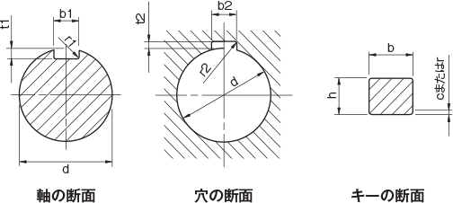
| b | h | c or r | Reference dimensions for b1 and b2 | Clamping type | Standard type | r1 and r2 | t1 | t2 | ||||||||
| Reference dimensions | Tolerance (h9) | Reference dimension | Tolerance | Tolerance for b1 and b2 (P9) | Tolerance for b1 (N9) | Tolerance for b2 (Js9) | Reference Dimensions | Tolerance | Reference dimension | Tolerance | ||||||
| 2×2 | 6–8 | 2 | 0–0 .025 | 2 | 0–0 .025 | h9 | 0.16–0.25 | 2 | -0.006 -0.031 | -0.004 -0.029 | ±0.0125 | 0.08–0.16 | 1.2 | +0.1 0 | 1.0 | +0.1 0 |
| 3×3 | 8–10 | 3 | 3 | 3 | 1.8 | 1.4 | ||||||||||
| 4×4 | 10–12 | 4 | 0–0 .030 | 4 | 0–0 .030 | 4 | -0.012 -0.042 | 0–0 .030 | ±0.0150 | 2.5 | 1.8 | |||||
| 5×5 | 12–17 | 5 | 5 | 0.25–0.40 | 5 | 0.16–0.25 | 3.0 | 2.3 | ||||||||
| 6×6 | 17–22 | 6 | 6 | 6 | 3.5 | 2.8 | ||||||||||
| 8×7 | 22–30 | 8 | 0–0 .036 | 7 | 0–0 .090 | h11 | 8 | -0.015 -0.051 | 0–0 .036 | ±0.0180 | 4.0 | +0.2 0 | 3.3 | +0.2 0 | ||
| 10×8 | 30–38 | 10 | 8 | 0.40–0.60 | 10 | 0.25–0.40 | 5.0 | 3.3 | ||||||||
| 12×8 | 38–44 | 12 | 0–0 .043 | 8 | 12 | -0.018 -0.061 | 0–0 .043 | ±0.0215 | 5.0 | 3.3 | ||||||
| 14×9 | 44–50 | 14 | 9 | 14 | 5.5 | 3.8 | ||||||||||
| 16×10 | 50–58 | 16 | 10 | 16 | 6.0 | 4.3 | ||||||||||
| 18×11 | 58–65 | 18 | 11 | 0–0 .110 | 18 | 7.0 | 4.4 | |||||||||
| 20×12 | 65–75 | 20 | 0–0 .052 | 12 | 0.60–0.80 | 20 | -0.022 -0.074 | 0–0 .052 | ±0.0260 | 0.40–0.60 | 7.5 | 4.9 | ||||
| 22×14 | 75–85 | 22 | 14 | 22 | 9.0 | 5.4 | ||||||||||
| 25×14 | 85–95 | 25 | 14 | 25 | 9.0 | 5.4 | ||||||||||
| 28×16 | 95–110 | 28 | 16 | 28 | 10.0 | 6.4 | ||||||||||
| 32×18 | 110–130 | 32 | 0–0 .062 | 18 | 32 | -0.026 -0.088 | 0–0 .062 | ±0.0310 | 11.0 | 7.4 | ||||||
Former JIS Standards
JIS Old Standard Type 1 (Excerpt from JIS B 1301-1959)
| Key nominal dimensions b × h | Applicable shaft diameter d | Key dimensions | Keyway dimensions | |||||||||||
|---|---|---|---|---|---|---|---|---|---|---|---|---|---|---|
| b | h | c or r | Reference dimensions for b1 and b2 | b1 tolerance (H8) | b2 tolerance (F7) | r1 and r2 | t1 | t2 | ||||||
| Reference dimension | Tolerance (p7) | Reference dimension | Tolerance (h9) | Reference dimension | Tolerance | Reference dimension | Tolerance | |||||||
| 4×4 | 10 or more, 13 or less | 4 | +0.024 +0.012 | 4 | 0–0 .030 | 0.5 | 4 | +0.018 0 | +0.022 +0.010 | 0.4 | 2.5 | +0.05 0 | 1.5 | +0.05 0 |
| 5×5 | Greater than 13 and less than or equal to 20 | 5 | 5 | 5 | 3 | 2 | ||||||||
| 7×7 | Over 20 and 30 or less | 7 | +0.030 +0.015 | 7 | 0–0 .036 | 7 | +0.022 0 | +0.028 +0.013 | 4 | 3 | ||||
| 10×8 | Over 30 and 40 or less | 10 | 8 | 0.8 | 10 | 0.6 | 4.5 | 3.5 | ||||||
| 12×8 | Over 40 and 50 or less | 12 | +0.036 +0.018 | 8 | 12 | +0.027 0 | +0.034 +0.016 | 4.5 | 3.5 | |||||
| 15×10 | Over 50 and 60 or less | 15 | 10 | 15 | 5 | 5 | ||||||||
| 18×12 | Over 60 and 70 or less | 18 | 12 | 0–0 .043 | 1.2 | 18 | 1.0 | 6 | 6 | |||||
| 20×13 | Over 70 and 80 or less | 20 | +0.043 +0.022 | 13 | 20 | +0.033 0 | +0.041 +0.020 | 7 | 6 | |||||
| 24×16 | Over 80 and 95 or less | 24 | 16 | 24 | 8 | 8 | ||||||||
| 28×18 | Over 95 and 110 or less | 28 | 18 | 28 | 9 | 9 | ||||||||
| 32×20 | Over 110 and 125 or less | 32 | +0.051 +0.026 | 20 | 0–0 .052 | 2 | 32 | +0.039 0 | +0.050 +0.025 | 1.6 | 10 | 10 | ||
JIS Old Standard Type 2 (Excerpt from JIS B 1301-1959)
| Key nominal dimensions b × h | Applicable shaft diameter d | Key dimensions | Keyway dimensions | |||||||||||
|---|---|---|---|---|---|---|---|---|---|---|---|---|---|---|
| b | h | c or r | Reference dimensions for b1 and b2 | b1 tolerance (H9) | b2 tolerance (E9) | r1 and r2 | t1 | t2 | ||||||
| Reference dimension | Tolerance (h8) | Reference dimension | Tolerance (h10) | Reference dimension | Tolerance | Nominal dimension | Tolerance | |||||||
| 4×4 | 10 or more, 13 or less | 4 | 0–0 .018 | 4 | 0–0 .048 | 0.5 | 4 | +0.030 0 | +0.050 +0.020 | 0.4 | 2.5 | +0.1 0 | 1.5 | +0.1 0 |
| 5×5 | Greater than 13 and less than or equal to 20 | 5 | 5 | 5 | 3 | 2 | ||||||||
| 7×7 | Over 20 and 30 or less | 7 | 0–0 .022 | 7 | 0–0 .058 | 7 | +0.036 0 | +0.061 +0.025 | 4 | 3 | ||||
| 10×8 | Over 30 and 40 or less | 10 | 8 | 0.8 | 10 | 0.6 | 4.5 | 3.5 | ||||||
| 12×8 | Over 40 and 50 or less | 12 | 0–0 .027 | 8 | 12 | +0.043 0 | +0.075 +0.032 | 4.5 | 3.5 | |||||
| 15×10 | Over 50 and 60 or less | 15 | 10 | 15 | 5 | 5 | ||||||||
| 18×12 | Over 60 and 70 or less | 18 | 12 | 0–0 .070 | 1.2 | 18 | 1.0 | 6 | 6 | |||||
| 20×13 | Over 70 and 80 or less | 20 | 0–0 .033 | 13 | 20 | +0.052 0 | +0.092 +0.040 | 7 | 6 | |||||
| 24×16 | Over 80 and 95 or less | 24 | 16 | 24 | 8 | 8 | ||||||||
| 28×18 | Over 95 and 110 or less | 28 | 18 | 28 | 9 | 9 | ||||||||
| 32×20 | Over 110 and 125 or less | 32 | 0–0 .039 | 20 | 0–0 .084 | 2 | 32 | +0.062 0 | +0.112 +0.050 | 1.6 | 10 | 10 | ||
Other Technical Documents
You can download the following technical documents as a single PDF file.
Specifications
Hole Machining, Tolerances, and Fits
Calculations, Conversions, Formulas, and Units
Machine Elements
- Hexagon Socket Head Cap Screw Standards List | Excerpt from JIS B 1176
- Shapes and Dimensions of Hexagon Socket Set Screws (Excerpt from JIS B 1177-1997)
- Shapes and Dimensions of Hex Bolts (Component Grade A) (Excerpt from JIS B 1180-1985)
- How to Use Hex Socket Set Screws
- Mechanical Properties of Steel Bolts and Screws (Excerpt from JIS B 1051-2000)
- Shapes and Dimensions of Hexagonal Wrenches (Hex Wrenches/L-Wrenches/Hex Wrenches) (Excerpt from JIS B 4648:2008)
- List of Standards for Dimensions and Tolerances of Parallel Keys and Keyways (Excerpt from JIS B 1301-1996/JIS B 1301-1959 [Old JIS])
- Snap Rings (C-Type Retaining Rings/C-Rings) Standards and Dimensions List (Excerpt from JIS B 2804-2010)
- Shim Dimensions
- Ball Bearing Standard Dimensions Table - JIS Excerpt
Material Properties
Terminology
- Glossary of Electromagnetic Clutch and Electromagnetic Brake Terms (Excerpt from JIS B 1404-1:2005)
- Glossary of Screw Terms (JIS B 0101:2013)
- Glossary of Fit Tolerances (Excerpt from JIS B 0401-1:2016)
- Glossary of Terms for Chains, Sprockets, and Accessories (Excerpt from JIS B 1812:2015)
- Glossary of Friction Belt Transmission Terms (Excerpt from JIS B 1860:2018)
- Technical Drawing—Terminology (Excerpt from JIS Z 8114:1999)