Snap Ring (C-Ring) Standards and Dimensions Table (Excerpt from JIS B 2804-2010)
2026/05/07
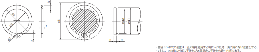
[For Shafts] Dimensions and Shape of C-Clips / Dimensions and Shape of Shaft Grooves
Unit [mm]
| Nominal | Retaining Ring | Applicable shaft (for reference) | |||||||||||||
|---|---|---|---|---|---|---|---|---|---|---|---|---|---|---|---|
| Column 1 | Column 2 | d3 | t | b | a | d0 | d5 | d1 | d2 | m | n | ||||
| Reference dimension | Tolerance | Reference dimension | Tolerance | Approx. | Approx. | Minimum | Reference dimension | Tolerance | Reference Dimensions | Tolerance | Minimum | ||||
| 10 | 9.3 | ±0.15 | 1 | ±0.05 | 1.6 | 3.0 | 1.2 | 17 | 10 | 9.6 | 0–0 .09 | 1.15 | +0.14 0 | 1.5 | |
| 11 | 10.2 | 1.8 | 3.1 | 18 | 11 | 10.5 | 0–0 .11 | ||||||||
| 12 | 11.1 | ±0.18 | 1.8 | 3.2 | 1.5 | 19 | 12 | 11.5 | |||||||
| 14 | 12.9 | 2.0 | 3.4 | 1.7 | 22 | 14 | 13.4 | ||||||||
| 15 | 13.8 | 2.1 | 3.5 | 23 | 15 | 14.3 | |||||||||
| 16 | 14.7 | 2.2 | 3.6 | 24 | 16 | 15.2 | |||||||||
| 17 | 15.7 | 2.2 | 3.7 | 25 | 17 | 16.2 | |||||||||
| 18 | 16.5 | 1.2 | ±0.06 | 2.6 | 3.8 | 26 | 18 | 17.0 | 1.35 | ||||||
| 19 | 17.5 | 2.7 | 3.8 | 2 | 27 | 19 | 18.0 | ||||||||
| 20 | 18.5 | ±0.20 | 2.7 | 3.9 | 28 | 20 | 19.0 | 0–0 .21 | |||||||
| 22 | 20.5 | 2.7 | 4.1 | 31 | 22 | 21.0 | |||||||||
| 24 | 22.2 | 3.1 | 4.2 | 33 | 24 | 22.9 | |||||||||
| 25 | 23.2 | 3.1 | 4.3 | 34 | 25 | 23.9 | |||||||||
| 26 | 24.2 | 3.1 | 4.4 | 35 | 26 | 24.9 | |||||||||
| 28 | 25.9 | 1.5 | 3.1 | 4.6 | 38 | 28 | 26.6 | 1.65 | |||||||
| 30 | 27.9 | 3.5 | 4.8 | 40 | 30 | 28.6 | |||||||||
| 32 | 29.6 | 3.5 | 5.0 | 2.5 | 43 | 32 | 30.3 | 0–0 .25 | |||||||
| 35 | 32.2 | ±0.25 | 4.0 | 5.4 | 46 | 35 | 33.0 | ||||||||
| 36 | 33.2 | 1.75 | ±0.07 | 4.0 | 5.4 | 47 | 36 | 34.0 | 1.90 | 2 | |||||
| 38 | 35.2 | 4.5 | 5.6 | 50 | 38 | 36.0 | |||||||||
| 40 | 37.0 | ±0.40 | 4.5 | 5.8 | 53 | 40 | 38.0 | ||||||||
| 42 | 38.5 | 4.5 | 6.2 | 55 | 42 | 39.5 | |||||||||
| 45 | 41.5 | 4.8 | 6.3 | 58 | 45 | 42.5 | |||||||||
| 48 | 44.5 | 4.8 | 6.5 | 62 | 48 | 45.5 | |||||||||
| 50 | 45.8 | 2 | 5.0 | 6.7 | 64 | 50 | 47.0 | 2.2 | |||||||
| 55 | 50.8 | ±0.45 | 5.0 | 7.0 | 70 | 55 | 52.0 | 0–0 .30 | |||||||
| 56 | 51.8 | 5.0 | 7.0 | 71 | 56 | 53.0 | |||||||||
| 60 | 55.8 | 5.5 | 7.2 | 75 | 60 | 57.0 | |||||||||
| 65 | 60.8 | 2.5 | ±0.08 | 6.4 | 7.4 | 81 | 65 | 62.0 | 2.7 | 2.5 | |||||
| 70 | 65.5 | 6.4 | 7.8 | 86 | 70 | 67.0 | |||||||||
| 75 | 70.5 | 7.0 | 7.9 | 92 | 75 | 72.0 | |||||||||
| 80 | 74.5 | 7.4 | 8.2 | 97 | 80 | 76.5 | |||||||||
| 85 | 79.5 | 3 | ±0.09 | 8.0 | 8.4 | 3 | 103 | 85 | 81.5 | 0–0 .35 | 3.2 | +0.18 0 | 3 | ||
| 90 | 84.5 | ±0.55 | 8.0 | 8.7 | 108 | 90 | 86.5 | ||||||||
| 95 | 89.5 | 8.6 | 9.1 | 114 | 95 | 91.5 | |||||||||
| 100 | 94.5 | 9.0 | 9.5 | 119 | 100 | 96.5 | |||||||||
| 105 | 98.0 | 4 | 9.5 | 9.8 | 125 | 105 | 101.0 | 0–0 .54 | 4.2 | 4 | |||||
| 110 | 103.0 | 9.5 | 10.0 | 131 | 110 | 106.0 | |||||||||
| 120 | 113.0 | 10.3 | 10.9 | 143 | 120 | 116.0 | |||||||||
- b is the maximum width of the retaining ring's annular section.
- The minimum width of the retaining ring’s annular section should preferably be greater than the thickness t. Furthermore, d4 should preferably be calculated as d4 = d3 + (1.4 to 1.5)b.
- The dimensions of the applicable shafts are provided for reference only.
- When assigning names, prioritize the entries in Column 1, and use Column 2 if necessary.
- The standard thickness of 1.5 may be changed to 1.6 by agreement between the parties to the transaction. However, in this case, m shall be 1.75.
- The standard thickness of 1.75 may be set at 1.8 by agreement between the parties to the transaction. However, in this case, m shall be set at 1.95.
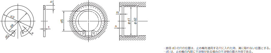
[For Holes] Dimensions and Shape of C-Clips / Dimensions and Shape of Grooves on the Hole Side
Unit [mm]
| Nominal | Retaining Ring | Applicable Hole (Reference) | |||||||||||||
|---|---|---|---|---|---|---|---|---|---|---|---|---|---|---|---|
| Column 1 | Column 2 | d3 | t | b | a | d0 | d5 | d1 | d2 | m | n | ||||
| Reference dimension | Tolerance | Reference dimension | Tolerance | Approx. | Approx. | Minimum | Reference dimension | Tolerance | Reference Dimensions | Tolerance | Minimum | ||||
| 10 | 10.7 | ±0.18 | 1 | ±0.05 | 1.8 | 3.1 | 1.2 | 3 | 10 | 10.4 | +0.11 0 | 1.15 | +0.14 0 | 1.5 | |
| 11 | 11.8 | 1.8 | 3.2 | 4 | 11 | 11.4 | |||||||||
| 12 | 13.0 | 1.8 | 3.3 | 1.5 | 5 | 12 | 12.5 | ||||||||
| 13 | 14.1 | 1.8 | 3.5 | 6 | 13 | 13.6 | |||||||||
| 14 | 15.1 | 2.0 | 3.6 | 1.7 | 7 | 14 | 14.6 | ||||||||
| 15 | 16.2 | 2.0 | 3.6 | 8 | 15 | 15.7 | |||||||||
| 16 | 17.3 | 2.0 | 3.7 | 8 | 16 | 16.8 | |||||||||
| 17 | 18.3 | ±0.20 | 2.0 | 3.8 | 9 | 17 | 17.8 | ||||||||
| 18 | 19.5 | 2.5 | 4.0 | 10 | 18 | 19.0 | +0.21 0 | ||||||||
| 19 | 20.5 | 2.5 | 4.0 | 2 | 11 | 19 | 20.0 | ||||||||
| 20 | 21.5 | 2.5 | 4.0 | 12 | 20 | 21.0 | |||||||||
| 22 | 23.5 | 2.5 | 4.1 | 13 | 22 | 23.0 | |||||||||
| 24 | 25.9 | 1.2 | ±0.06 | 2.5 | 4.3 | 15 | 24 | 25.2 | 1.35 | ||||||
| 25 | 26.9 | 3.0 | 4.4 | 16 | 25 | 26.2 | |||||||||
| 26 | 27.9 | 3.0 | 4.6 | 16 | 26 | 27.2 | |||||||||
| 28 | 30.1 | ±0.25 | 3.0 | 4.6 | 18 | 28 | 29.4 | ||||||||
| 30 | 32.1 | 3.0 | 4.7 | 20 | 30 | 31.4 | +0.25 0 | ||||||||
| 32 | 34.4 | 3.5 | 5.2 | 2.5 | 21 | 32 | 33.7 | ||||||||
| 35 | 37.8 | 1.5 | 3.5 | 5.2 | 24 | 35 | 37.0 | 1.65 | 2 | ||||||
| 36 | 38.8 | 3.5 | 5.2 | 25 | 36 | 38.0 | |||||||||
| 37 | 39.8 | 3.5 | 5.2 | 26 | 37 | 39.0 | |||||||||
| 38 | 40.8 | 4.0 | 5.3 | 27 | 38 | 40.0 | |||||||||
| 40 | 43.5 | ±0.4 | 1.75 | ±0.07 | 4.0 | 5.7 | 28 | 40 | 42.5 | 1.90 | |||||
| 42 | 45.5 | 4.0 | 5.8 | 30 | 42 | 44.5 | |||||||||
| 45 | 48.5 | 4.5 | 5.9 | 33 | 45 | 47.5 | |||||||||
| 47 | 50.5 | ±0.45 | 4.5 | 6.1 | 34 | 47 | 49.5 | ||||||||
| 48 | 51.5 | 4.5 | 6.2 | 35 | 48 | 50.5 | +0.30 | ||||||||
| 50 | 54.2 | 2 | 4.5 | 6.5 | 37 | 50 | 53.0 | 2.2 | |||||||
| 52 | 56.2 | 5.1 | 6.5 | 39 | 52 | 55.0 | |||||||||
| 55 | 59.2 | 5.1 | 6.5 | 41 | 55 | 58.0 | |||||||||
| 56 | 60.2 | 5.1 | 6.6 | 42 | 56 | 59.0 | |||||||||
| 60 | 64.2 | 5.5 | 6.8 | 46 | 60 | 63.0 | |||||||||
| 62 | 66.2 | 5.5 | 6.9 | 48 | 62 | 65.0 | |||||||||
| 63 | 67.2 | 5.5 | 6.9 | 49 | 63 | 66.0 | |||||||||
| 65 | 69.2 | 2.5 | ±0.08 | 5.5 | 7.0 | 50 | 65 | 68.0 | 2.7 | 2.5 | |||||
| 68 | 72.5 | 6.0 | 7.4 | 53 | 68 | 71.0 | |||||||||
| 70 | 74.5 | 6.0 | 7.4 | 55 | 70 | 73.0 | |||||||||
| 72 | 76.5 | 6.6 | 7.4 | 57 | 72 | 75.0 | |||||||||
| 75 | 79.5 | 6.6 | 7.8 | 60 | 75 | 78.0 | |||||||||
| 80 | 85.5 | ±0.55 | 7.0 | 8.0 | 64 | 80 | 83.5 | +0.35 | |||||||
| 85 | 90.5 | 3 | ±0.09 | 7.0 | 8.0 | 3 | 69 | 85 | 88.5 | 3.2 | +0.18 0 | 3 | |||
| 90 | 95.5 | 7.6 | 8.3 | 73 | 90 | 93.5 | |||||||||
| 95 | 100.5 | 8.0 | 8.5 | 77 | 95 | 98.5 | |||||||||
| 100 | 105.5 | 8.3 | 8.8 | 82 | 100 | 103.5 | |||||||||
| 105 | 112.0 | 4 | 8.9 | 9.1 | 86 | 105 | 109.0 | +0.54 | 4.2 | 4 | |||||
| 110 | 117.0 | 8.9 | 10.2 | 89 | 110 | 114.0 | |||||||||
| 112 | 119.0 | 8.9 | 10.2 | 90 | 112 | 116.0 | |||||||||
| 115 | 122.0 | ±0.65 | 9.5 | 10.2 | 94 | 115 | 119.0 | ||||||||
| 120 | 127.0 | 9.5 | 10.7 | 98 | 120 | 124.0 | +0.63 | ||||||||
| 125 | 132.0 | 10.0 | 10.7 | 3.5 | 103 | 125 | 129.0 | ||||||||
- b is the maximum width of the retaining ring's annular section.
- The minimum width of the retaining ring’s annular section should preferably be greater than the thickness t. Furthermore, d4 should preferably be calculated as d4 = d3 – (1.4 to 1.5)b.
- The dimensions of the holes to be drilled are provided for reference only.
- When assigning names, prioritize the entries in Column 1, and use Column 2 if necessary.
- The standard thickness of 1.5 may be changed to 1.6 by agreement between the parties to the transaction. However, in this case, m shall be 1.75.
- The standard thickness of 1.75 may be set at 1.8 by agreement between the parties to the transaction. However, in this case, m shall be set at 1.95.
Specifications
Hole Machining, Tolerances, and Fits
Calculations, Conversions, Formulas, and Units
Machine Elements
- Hexagon Socket Head Cap Screw Standards List | Excerpt from JIS B 1176
- Shapes and Dimensions of Hexagon Socket Set Screws (Excerpt from JIS B 1177-1997)
- Shapes and Dimensions of Hex Bolts (Component Grade A) (Excerpt from JIS B 1180-1985)
- How to Use Hex Socket Set Screws
- Mechanical Properties of Steel Bolts and Screws (Excerpt from JIS B 1051-2000)
- Shapes and Dimensions of Hexagonal Wrenches (Hex Wrenches/L-Wrenches/Hex Wrenches) (Excerpt from JIS B 4648:2008)
- List of Standards for Dimensions and Tolerances of Parallel Keys and Keyways (Excerpt from JIS B 1301-1996/JIS B 1301-1959 [Old JIS])
- Snap Rings (C-Type Retaining Rings/C-Rings) Standards and Dimensions List (Excerpt from JIS B 2804-2010)
- Shim Dimensions
- Ball Bearing Standard Dimensions Table - JIS Excerpt
Material Properties
Terminology
- Glossary of Electromagnetic Clutch and Electromagnetic Brake Terms (Excerpt from JIS B 1404-1:2005)
- Glossary of Screw Terms (JIS B 0101:2013)
- Glossary of Fit Tolerances (Excerpt from JIS B 0401-1:2016)
- Glossary of Terms for Chains, Sprockets, and Accessories (Excerpt from JIS B 1812:2015)
- Glossary of Friction Belt Transmission Terms (Excerpt from JIS B 1860:2018)
- Technical Drawing—Terminology (Excerpt from JIS Z 8114:1999)