日本語
日本語 English
 Deutsch
 中文
中文 한국어
한국어


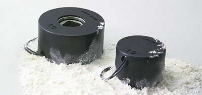
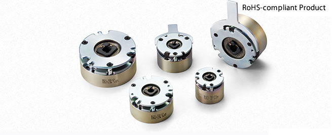
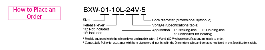
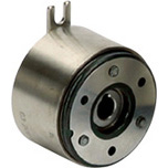
BXW Models

![]()
BXW-□-□L/-H/-S Types
[Specifications] BXW-□-□L (Braking use)
| Model | Size | Static friction torque Ts [N・m] | Coil (at 20℃) | Heat resistance class | Lead wire | Max. rotation speed [min-1] | Rotating part moment of inertia J [kg・m2] | Allowable braking energy rate Pbaℓ [W] | Total braking energy ET [J] | Armature pull-in time ta [s] | Armature release time tar [s] | Mass [kg] | ||||
|---|---|---|---|---|---|---|---|---|---|---|---|---|---|---|---|---|
| Voltage [V] | Wattage [W] | Current [A] | Resistance [Ω] | UL style | Size | |||||||||||
| BXW-01-10L | 01 | 0.12 | 12 | 5.0 | 0.417 | 28.8 | F | UL3398 | AWG26 | 5000 | 0.6×10⁻⁶ | 2.5 | 1.5×10⁶ | 0.008 | 0.015 | 0.2 |
| 24 | 5.0 | 0.208 | 115 | F | ||||||||||||
| 45 | 5.0 | 0.111 | 405 | F | ||||||||||||
| 90 | 5.0 | 0.056 | 1622 | F | ||||||||||||
| 180 | 5.0 | 0.028 | 6486 | F | ||||||||||||
| BXW-02-10L | 02 | 0.25 | 12 | 6.6 | 0.550 | 21.8 | F | UL3398 | AWG26 | 5000 | 1.9×10⁻⁶ | 5.0 | 3.0×10⁶ | 0.008 | 0.015 | 0.3 |
| 24 | 6.6 | 0.275 | 87.3 | F | ||||||||||||
| 45 | 6.6 | 0.147 | 307 | F | ||||||||||||
| 90 | 6.6 | 0.073 | 1228 | F | ||||||||||||
| 180 | 6.6 | 0.037 | 4912 | F | ||||||||||||
| BXW-02-12L | 02 | 0.25 | 12 | 6.6 | 0.550 | 21.8 | F | UL3398 | AWG26 | 5000 | 1.9×10⁻⁶ | 5.0 | 3.0×10⁶ | 0.008 | 0.015 | 0.3 |
| 24 | 6.6 | 0.275 | 87.3 | F | ||||||||||||
| 45 | 6.6 | 0.147 | 307 | F | ||||||||||||
| 90 | 6.6 | 0.073 | 1228 | F | ||||||||||||
| 180 | 6.6 | 0.037 | 4912 | F | ||||||||||||
| BXW-03-10L | 03 | 0.50 | 12 | 9.0 | 0.750 | 16.0 | F | UL3398 | AWG26 | 5000 | 3.8×10⁻⁶ | 10.0 | 4.5×10⁶ | 0.025 | 0.025 | 0.4 |
| 24 | 9.0 | 0.375 | 64.0 | F | ||||||||||||
| 45 | 8.2 | 0.182 | 247 | F | ||||||||||||
| 90 | 8.2 | 0.091 | 988 | F | ||||||||||||
| 180 | 8.2 | 0.046 | 3954 | F | ||||||||||||
| BXW-03-12L | 03 | 0.50 | 12 | 9.0 | 0.750 | 16.0 | F | UL3398 | AWG26 | 5000 | 3.8×10⁻⁶ | 10.0 | 4.5×10⁶ | 0.025 | 0.025 | 0.4 |
| 24 | 9.0 | 0.375 | 64.0 | F | ||||||||||||
| 45 | 8.2 | 0.182 | 247 | F | ||||||||||||
| 90 | 8.2 | 0.091 | 988 | F | ||||||||||||
| 180 | 8.2 | 0.046 | 3954 | F | ||||||||||||
| BXW-04-10L | 04 | 1.00 | 12 | 11.5 | 0.958 | 12.5 | F | UL3398 | AWG22 | 5000 | 12.0×10⁻⁶ | 20.0 | 7.0×10⁶ | 0.030 | 0.030 | 0.6 |
| 24 | 11.5 | 0.479 | 50.1 | F | ||||||||||||
| 45 | 10.0 | 0.222 | 203 | F | ||||||||||||
| 90 | 10.0 | 0.111 | 810 | F | ||||||||||||
| 180 | 10.0 | 0.056 | 3241 | F | ||||||||||||
| BXW-04-12L | 04 | 1.00 | 12 | 11.5 | 0.958 | 12.5 | F | UL3398 | AWG22 | 5000 | 12.0×10⁻⁶ | 20.0 | 7.0×10⁶ | 0.030 | 0.030 | 0.6 |
| 24 | 11.5 | 0.479 | 50.1 | F | ||||||||||||
| 45 | 10.0 | 0.222 | 203 | F | ||||||||||||
| 90 | 10.0 | 0.111 | 810 | F | ||||||||||||
| 180 | 10.0 | 0.056 | 3241 | F | ||||||||||||
| BXW-05-10L | 05 | 2.00 | 12 | 13.0 | 1.083 | 11.1 | F | UL3398 | AWG22 | 5000 | 23.0×10⁻⁶ | 30.0 | 12.0×10⁶ | 0.035 | 0.035 | 0.8 |
| 24 | 13.0 | 0.542 | 44.3 | F | ||||||||||||
| 45 | 13.0 | 0.289 | 156 | F | ||||||||||||
| 90 | 13.0 | 0.144 | 623 | F | ||||||||||||
| 180 | 13.0 | 0.072 | 2492 | F | ||||||||||||
| BXW-05-12L | 05 | 2.00 | 12 | 13.0 | 1.083 | 11.1 | F | UL3398 | AWG22 | 5000 | 23.0×10⁻⁶ | 30.0 | 12.0×10⁶ | 0.035 | 0.035 | 0.8 |
| 24 | 13.0 | 0.542 | 44.3 | F | ||||||||||||
| 45 | 13.0 | 0.289 | 156 | F | ||||||||||||
| 90 | 13.0 | 0.144 | 623 | F | ||||||||||||
| 180 | 13.0 | 0.072 | 2492 | F | ||||||||||||
*Depending on the initial torque characteristics, break-in to condition the engaging surfaces may be required.
[Specifications] BXW-□-□H (Holding use)
| Model | Size | Static friction torque Ts [N・m] | Coil (at 20℃) | Heat resistance class | Lead wire | Max. rotation speed [min-1] | Rotating part moment of inertia J [kg・m2] | Allowable braking energy rate Pbaℓ [W] | Total braking energy ET [J] | Armature pull-in time ta [s] | Armature release time tar [s] | Mass [kg] | ||||
|---|---|---|---|---|---|---|---|---|---|---|---|---|---|---|---|---|
| Voltage [V] | Wattage [W] | Current [A] | Resistance [Ω] | UL style | Size | |||||||||||
| BXW-01-10H | 01 | 0.24 | 12 | 5.0 | 0.417 | 28.8 | F | UL3398 | AWG26 | 5000 | 0.6×10⁻⁶ | 0.5 | 0.2×10⁶ | 0.010 | 0.010 | 0.2 |
| 24 | 5.0 | 0.208 | 115 | F | ||||||||||||
| 45 | 5.0 | 0.111 | 405 | F | ||||||||||||
| 90 | 5.0 | 0.056 | 1622 | F | ||||||||||||
| 180 | 5.0 | 0.028 | 6486 | F | ||||||||||||
| BXW-02-10H | 02 | 0.50 | 12 | 6.6 | 0.550 | 21.8 | F | UL3398 | AWG26 | 5000 | 1.9×10⁻⁶ | 1.0 | 0.3×10⁶ | 0.010 | 0.010 | 0.3 |
| 24 | 6.6 | 0.275 | 87.3 | F | ||||||||||||
| 45 | 6.6 | 0.147 | 307 | F | ||||||||||||
| 90 | 6.6 | 0.073 | 1228 | F | ||||||||||||
| 180 | 6.6 | 0.037 | 4912 | F | ||||||||||||
| BXW-02-12H | 02 | 0.50 | 12 | 6.6 | 0.550 | 21.8 | F | UL3398 | AWG26 | 5000 | 1.9×10⁻⁶ | 1.0 | 0.3×10⁶ | 0.010 | 0.010 | 0.3 |
| 24 | 6.6 | 0.275 | 87.3 | F | ||||||||||||
| 45 | 6.6 | 0.147 | 307 | F | ||||||||||||
| 90 | 6.6 | 0.073 | 1228 | F | ||||||||||||
| 180 | 6.6 | 0.037 | 4912 | F | ||||||||||||
| BXW-03-10H | 03 | 1.00 | 12 | 9.0 | 0.750 | 16.0 | F | UL3398 | AWG26 | 5000 | 3.8×10⁻⁶ | 2.0 | 0.5×10⁶ | 0.035 | 0.020 | 0.4 |
| 24 | 9.0 | 0.375 | 64.0 | F | ||||||||||||
| 45 | 8.2 | 0.182 | 247 | F | ||||||||||||
| 90 | 8.2 | 0.091 | 988 | F | ||||||||||||
| 180 | 8.2 | 0.046 | 3954 | F | ||||||||||||
| BXW-03-12H | 03 | 1.00 | 12 | 9.0 | 0.750 | 16.0 | F | UL3398 | AWG26 | 5000 | 3.8×10⁻⁶ | 2.0 | 0.5×10⁶ | 0.035 | 0.020 | 0.4 |
| 24 | 9.0 | 0.375 | 64.0 | F | ||||||||||||
| 45 | 8.2 | 0.182 | 247 | F | ||||||||||||
| 90 | 8.2 | 0.091 | 988 | F | ||||||||||||
| 180 | 8.2 | 0.046 | 3954 | F | ||||||||||||
| BXW-04-10H | 04 | 2.00 | 12 | 11.5 | 0.958 | 12.5 | F | UL3398 | AWG22 | 5000 | 12.0×10⁻⁶ | 4.0 | 1.0×10⁶ | 0.040 | 0.025 | 0.6 |
| 24 | 11.5 | 0.479 | 50.1 | F | ||||||||||||
| 45 | 10.0 | 0.222 | 203 | F | ||||||||||||
| 90 | 10.0 | 0.111 | 810 | F | ||||||||||||
| 180 | 10.0 | 0.056 | 3241 | F | ||||||||||||
| BXW-04-12H | 04 | 2.00 | 12 | 11.5 | 0.958 | 12.5 | F | UL3398 | AWG22 | 5000 | 12.0×10⁻⁶ | 4.0 | 1.0×10⁶ | 0.040 | 0.025 | 0.6 |
| 24 | 11.5 | 0.479 | 50.1 | F | ||||||||||||
| 45 | 10.0 | 0.222 | 203 | F | ||||||||||||
| 90 | 10.0 | 0.111 | 810 | F | ||||||||||||
| 180 | 10.0 | 0.056 | 3241 | F | ||||||||||||
| BXW-05-10H | 05 | 4.00 | 12 | 13.0 | 1.083 | 11.1 | F | UL3398 | AWG22 | 5000 | 23.0×10⁻⁶ | 6.0 | 2.0×10⁶ | 0.045 | 0.030 | 0.8 |
| 24 | 13.0 | 0.542 | 44.3 | F | ||||||||||||
| 45 | 13.0 | 0.289 | 156 | F | ||||||||||||
| 90 | 13.0 | 0.144 | 623 | F | ||||||||||||
| 180 | 13.0 | 0.072 | 2492 | F | ||||||||||||
| BXW-05-12H | 05 | 4.00 | 12 | 13.0 | 1.083 | 11.1 | F | UL3398 | AWG22 | 5000 | 23.0×10⁻⁶ | 6.0 | 2.0×10⁶ | 0.045 | 0.030 | 0.8 |
| 24 | 13.0 | 0.542 | 44.3 | F | ||||||||||||
| 45 | 13.0 | 0.289 | 156 | F | ||||||||||||
| 90 | 13.0 | 0.144 | 623 | F | ||||||||||||
| 180 | 13.0 | 0.072 | 2492 | F | ||||||||||||
*The armature pull-in time and armature release time are measured during DC switching.
[Specifications] BXW-□-□S (Dedicated for holding)
| Model | Size | Static friction torque Ts [N・m] | Coil (at 20℃) | Heat resistance class | Lead wire | Max. rotation speed [min-1] | Rotating part moment of inertia J [kg・m2] | Allowable braking energy rate Pbaℓ [W] | Total braking energy ET [J] | Armature pull-in time ta [s] | Armature release time tar [s] | Mass [kg] | ||||
|---|---|---|---|---|---|---|---|---|---|---|---|---|---|---|---|---|
| Voltage [V] | Wattage [W] | Current [A] | Resistance [Ω] | UL style | Size | |||||||||||
| BXW-01-10S | 01 | 0.36 | 24 | 5.0 | 0.208 | 115 | F | UL3398 | AWG26 | 5000 | 0.6×10⁻⁶ | - | - | 0.025 | 0.010 | 0.2 |
| BXW-02-10S | 02 | 0.75 | 24 | 6.6 | 0.275 | 87.3 | F | UL3398 | AWG26 | 5000 | 1.9×10⁻⁶ | - | - | 0.030 | 0.010 | 0.3 |
| BXW-02-12S | 02 | 0.75 | 24 | 6.6 | 0.275 | 87.3 | F | UL3398 | AWG26 | 5000 | 1.9×10⁻⁶ | - | - | 0.030 | 0.010 | 0.3 |
| BXW-03-10S | 03 | 1.50 | 24 | 9.0 | 0.375 | 64.0 | F | UL3398 | AWG26 | 5000 | 3.8×10⁻⁶ | - | - | 0.035 | 0.020 | 0.4 |
| BXW-03-12S | 03 | 1.50 | 24 | 9.0 | 0.375 | 64.0 | F | UL3398 | AWG26 | 5000 | 3.8×10⁻⁶ | - | - | 0.035 | 0.020 | 0.4 |
| BXW-04-10S | 04 | 2.60 | 24 | 11.5 | 0.479 | 50.1 | F | UL3398 | AWG22 | 5000 | 12.0×10⁻⁶ | - | - | 0.040 | 0.025 | 0.6 |
| BXW-04-12S | 04 | 2.60 | 24 | 11.5 | 0.479 | 50.1 | F | UL3398 | AWG22 | 5000 | 12.0×10⁻⁶ | - | - | 0.040 | 0.025 | 0.6 |
| BXW-05-10S | 05 | 5.20 | 24 | 13.0 | 0.542 | 44.3 | F | UL3398 | AWG22 | 5000 | 23.0×10⁻⁶ | - | - | 0.045 | 0.030 | 0.8 |
| BXW-05-12S | 05 | 5.20 | 24 | 13.0 | 0.542 | 44.3 | F | UL3398 | AWG22 | 5000 | 23.0×10⁻⁶ | - | - | 0.045 | 0.030 | 0.8 |
*The armature pull-in time and armature release time are taken during DC switching.
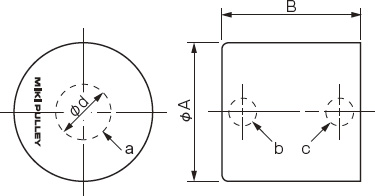
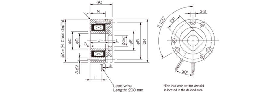
[Dimensions]
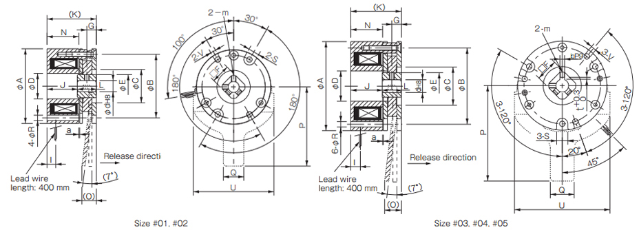
| Size | Radial direction dimensions | Axial direction dimentions | Bore dimensions | |||||||||||||||||||||
|---|---|---|---|---|---|---|---|---|---|---|---|---|---|---|---|---|---|---|---|---|---|---|---|---|
| A | B | C | D | E | S | V | R | F | m | O | P | Q | U | G | I | J | K | L | N | a | d | b | t | |
| 01 | 37 | 32 | 18 | 13.5 | 12.0 | 6 | 3 | 3 | 10 | M3 | - | - | - | - | 4.5 | 5.0 | 22.5 | 31.5 | 9 | 22.5 | 0.10 | 5 | - | - |
| 6 | - | - | ||||||||||||||||||||||
| 02 | 47 | 40 | 21 | 16.0 | 14.5 | 7 | 3.4 | 3.4 | 12 | M3 | 9(10.2) | 50 | 13 | 51 | 6.0 | 5.5 | 19.2 | 31.2 | 12 | 20.0 | 0.10 | 6 | - | - |
| 7 | - | - | ||||||||||||||||||||||
| 03 | 56 | 48 | 24 | 19.0 | 17.0 | 7 | 3.4 | 3.4 | 14 | M3 | 11(11.7) | 60 | 15 | 60 | 6.0 | 6.0 | 19.9 | 31.9 | 12 | 20.0 | 0.15 | 8 | - | - |
| 04 | 65 | 58 | 35 | 24.0 | 22.0 | 7 | 3.4 | 3.4 | 18 | M4 | 12(12.5) | 70 | 15 | 70 | 7.0 | 7.0 | 19.9 | 33.9 | 14 | 21.0 | 0.15 | 10 | 3 | 1.2 |
| 05 | 75 | 66 | 36 | 28.0 | 26.5 | 9 | 4.5 | 4.5 | 22 | M4 | 14(14.5) | 80 | 20 | 80 | 7.0 | 7.0 | 22.1 | 36.1 | 14 | 21.5 | 0.15 | 12 | 4 | 1.5 |
* There is no release lever option for size #01.
* The dimensions in parentheses ( ) are values for BXW- □ - □ S.
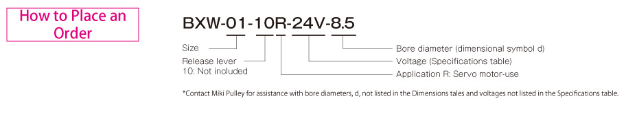
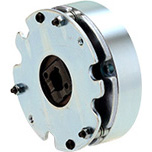
BXW-□-□R Types
[Specifications]
| Model | Size | Static friction torque Ts [N・m] | Coil (at 20℃) | Heat resistance class | Lead wire | Max. rotation speed [min-1] | Rotating part moment of inertia J [kg・m2] | Allowable braking energy rate Ebaℓ [J] | Total braking energy ET [J] | Armature pull-in time ta [s] | Armature release time tar [s] | Mass [kg] | ||||
|---|---|---|---|---|---|---|---|---|---|---|---|---|---|---|---|---|
| Voltage [V] | Wattage [W] | Current [A] | Resistance [Ω] | UL style | Size | |||||||||||
| BXW-01-10R | 01 | 0.3 | 24 | 6.1 | 0.254 | 94.4 | F | UL3398 | AWG26 | 6000 | 1.36×10⁻⁷ | 15 | 3000 | 0.035 | 0.020 | 0.1 |
| BXW-03-10R | 03 | 1.3 | 24 | 7.2 | 0.300 | 80.0 | F | UL3398 | AWG22 | 6000 | 1.17×10⁻⁶ | 87 | 17000 | 0.050 | 0.020 | 0.3 |
| BXW-05-10R | 05 | 2.5 | 24 | 8.0 | 0.333 | 72.0 | F | UL3398 | AWG22 | 6000 | 3.68×10⁻⁶ | 200 | 40000 | 0.060 | 0.020 | 0.5 |
*The armature pull-in time and armature release time are taken during DC switching.
[Dimensions]
| Size | Radial direction dimensions | Axial direction dimentions | Bore dimensions | |||||||||||||||||
|---|---|---|---|---|---|---|---|---|---|---|---|---|---|---|---|---|---|---|---|---|
| A | r | B | C | D | E | S | V | R | F | G | H | I | J | K | L | N | a | d | d max | |
| 01 | 33 | R0.5 | 26.5 | 16 | 9 | 14 | 7 | 3.4 | 32.5 | 12 | 0.2 | 4 | 19 | 25.5~26 | 30 | 4 | 22.8 | 0.1 | 8.5 | 8.5 |
| 03 | 48 | R1 | 42 | 26 | 14 | 23 | 8 | 3.4 | 47.5 | 19 | 0.2 | 4 | 18 | 25.5~26 | 30 | 4 | 22.6 | 0.1 | 11 | 15 |
| 05 | 64 | R1 | 56 | 28 | 22 | 31 | 8 | 4.5 | 63.5 | 25 | 0.2 | 4 | 16 | 25~25.5 | 30 | 4.5 | 21.3 | 0.1 | 16 | 20 |
*Bore diameters other than the standard bore diameters given above are also possible. d max indicates the maximum bore diameter with a round shaft.
*In addition to round bores, key processing can also be handled. Consult Miki Pulley for details.
*Dimensions, mounting and the like are not interchangeable with other BXW models.
![]()
![]()
![]()
![]()
![]()
![]()