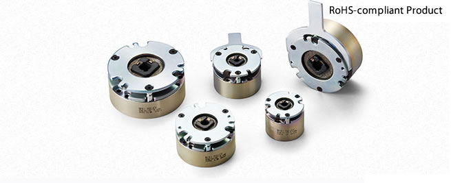
BXW Models Specifications
BXW-□-□L/-H/-S Types
[Specifications] BXW-□-□L (Braking use)
| Model | Size | Static friction torque Ts
[N・m] | Coil (at 20℃) | Heat resistance class | Lead wire | Max. rotation speed [min-1] | Rotating part moment of inertia J [kg・m2] | Allowable braking energy rate Pbaℓ [W] | Total braking energy ET [J] | Armature pull-in time ta [s] | Armature release time tar [s] | Mass [kg] |
|---|
| Voltage [V] | Wattage [W] | Current [A] | Resistance [Ω] | UL style | Size |
|---|
| BXW-01-10L | 01 | 0.12 | 12 | 5.0 | 0.417 | 28.8 | F | UL3398 | AWG26 | 5000 | 0.6×10⁻⁶ | 2.5 | 1.5×10⁶ | 0.008 | 0.015 | 0.2 |
|---|
| 24 | 5.0 | 0.208 | 115 | F |
| 45 | 5.0 | 0.111 | 405 | F |
| 90 | 5.0 | 0.056 | 1622 | F |
| 180 | 5.0 | 0.028 | 6486 | F |
| BXW-02-10L | 02 | 0.25 | 12 | 6.6 | 0.550 | 21.8 | F | UL3398 | AWG26 | 5000 | 1.9×10⁻⁶ | 5.0 | 3.0×10⁶ | 0.008 | 0.015 | 0.3 |
|---|
| 24 | 6.6 | 0.275 | 87.3 | F |
| 45 | 6.6 | 0.147 | 307 | F |
| 90 | 6.6 | 0.073 | 1228 | F |
| 180 | 6.6 | 0.037 | 4912 | F |
| BXW-02-12L | 02 | 0.25 | 12 | 6.6 | 0.550 | 21.8 | F | UL3398 | AWG26 | 5000 | 1.9×10⁻⁶ | 5.0 | 3.0×10⁶ | 0.008 | 0.015 | 0.3 |
|---|
| 24 | 6.6 | 0.275 | 87.3 | F |
| 45 | 6.6 | 0.147 | 307 | F |
| 90 | 6.6 | 0.073 | 1228 | F |
| 180 | 6.6 | 0.037 | 4912 | F |
| BXW-03-10L | 03 | 0.50 | 12 | 9.0 | 0.750 | 16.0 | F | UL3398 | AWG26 | 5000 | 3.8×10⁻⁶ | 10.0 | 4.5×10⁶ | 0.025 | 0.025 | 0.4 |
|---|
| 24 | 9.0 | 0.375 | 64.0 | F |
| 45 | 8.2 | 0.182 | 247 | F |
| 90 | 8.2 | 0.091 | 988 | F |
| 180 | 8.2 | 0.046 | 3954 | F |
| BXW-03-12L | 03 | 0.50 | 12 | 9.0 | 0.750 | 16.0 | F | UL3398 | AWG26 | 5000 | 3.8×10⁻⁶ | 10.0 | 4.5×10⁶ | 0.025 | 0.025 | 0.4 |
|---|
| 24 | 9.0 | 0.375 | 64.0 | F |
| 45 | 8.2 | 0.182 | 247 | F |
| 90 | 8.2 | 0.091 | 988 | F |
| 180 | 8.2 | 0.046 | 3954 | F |
| BXW-04-10L | 04 | 1.00 | 12 | 11.5 | 0.958 | 12.5 | F | UL3398 | AWG22 | 5000 | 12.0×10⁻⁶ | 20.0 | 7.0×10⁶ | 0.030 | 0.030 | 0.6 |
|---|
| 24 | 11.5 | 0.479 | 50.1 | F |
| 45 | 10.0 | 0.222 | 203 | F |
| 90 | 10.0 | 0.111 | 810 | F |
| 180 | 10.0 | 0.056 | 3241 | F |
| BXW-04-12L | 04 | 1.00 | 12 | 11.5 | 0.958 | 12.5 | F | UL3398 | AWG22 | 5000 | 12.0×10⁻⁶ | 20.0 | 7.0×10⁶ | 0.030 | 0.030 | 0.6 |
|---|
| 24 | 11.5 | 0.479 | 50.1 | F |
| 45 | 10.0 | 0.222 | 203 | F |
| 90 | 10.0 | 0.111 | 810 | F |
| 180 | 10.0 | 0.056 | 3241 | F |
| BXW-05-10L | 05 | 2.00 | 12 | 13.0 | 1.083 | 11.1 | F | UL3398 | AWG22 | 5000 | 23.0×10⁻⁶ | 30.0 | 12.0×10⁶ | 0.035 | 0.035 | 0.8 |
|---|
| 24 | 13.0 | 0.542 | 44.3 | F |
| 45 | 13.0 | 0.289 | 156 | F |
| 90 | 13.0 | 0.144 | 623 | F |
| 180 | 13.0 | 0.072 | 2492 | F |
| BXW-05-12L | 05 | 2.00 | 12 | 13.0 | 1.083 | 11.1 | F | UL3398 | AWG22 | 5000 | 23.0×10⁻⁶ | 30.0 | 12.0×10⁶ | 0.035 | 0.035 | 0.8 |
|---|
| 24 | 13.0 | 0.542 | 44.3 | F |
| 45 | 13.0 | 0.289 | 156 | F |
| 90 | 13.0 | 0.144 | 623 | F |
| 180 | 13.0 | 0.072 | 2492 | F |
*Depending on the initial torque characteristics, break-in to condition the engaging surfaces may be required.
[Specifications] BXW-□-□H (Holding use)
| Model | Size | Static friction torque Ts
[N・m] | Coil (at 20℃) | Heat resistance class | Lead wire | Max. rotation speed [min-1] | Rotating part moment of inertia J [kg・m2] | Allowable braking energy rate Pbaℓ [W] | Total braking energy ET [J] | Armature pull-in time ta [s] | Armature release time tar [s] | Mass [kg] |
|---|
| Voltage [V] | Wattage [W] | Current [A] | Resistance [Ω] | UL style | Size |
|---|
| BXW-01-10H | 01 | 0.24 | 12 | 5.0 | 0.417 | 28.8 | F | UL3398 | AWG26 | 5000 | 0.6×10⁻⁶ | 0.5 | 0.2×10⁶ | 0.010 | 0.010 | 0.2 |
|---|
| 24 | 5.0 | 0.208 | 115 | F |
| 45 | 5.0 | 0.111 | 405 | F |
| 90 | 5.0 | 0.056 | 1622 | F |
| 180 | 5.0 | 0.028 | 6486 | F |
| BXW-02-10H | 02 | 0.50 | 12 | 6.6 | 0.550 | 21.8 | F | UL3398 | AWG26 | 5000 | 1.9×10⁻⁶ | 1.0 | 0.3×10⁶ | 0.010 | 0.010 | 0.3 |
|---|
| 24 | 6.6 | 0.275 | 87.3 | F |
| 45 | 6.6 | 0.147 | 307 | F |
| 90 | 6.6 | 0.073 | 1228 | F |
| 180 | 6.6 | 0.037 | 4912 | F |
| BXW-02-12H | 02 | 0.50 | 12 | 6.6 | 0.550 | 21.8 | F | UL3398 | AWG26 | 5000 | 1.9×10⁻⁶ | 1.0 | 0.3×10⁶ | 0.010 | 0.010 | 0.3 |
|---|
| 24 | 6.6 | 0.275 | 87.3 | F |
| 45 | 6.6 | 0.147 | 307 | F |
| 90 | 6.6 | 0.073 | 1228 | F |
| 180 | 6.6 | 0.037 | 4912 | F |
| BXW-03-10H | 03 | 1.00 | 12 | 9.0 | 0.750 | 16.0 | F | UL3398 | AWG26 | 5000 | 3.8×10⁻⁶ | 2.0 | 0.5×10⁶ | 0.035 | 0.020 | 0.4 |
|---|
| 24 | 9.0 | 0.375 | 64.0 | F |
| 45 | 8.2 | 0.182 | 247 | F |
| 90 | 8.2 | 0.091 | 988 | F |
| 180 | 8.2 | 0.046 | 3954 | F |
| BXW-03-12H | 03 | 1.00 | 12 | 9.0 | 0.750 | 16.0 | F | UL3398 | AWG26 | 5000 | 3.8×10⁻⁶ | 2.0 | 0.5×10⁶ | 0.035 | 0.020 | 0.4 |
|---|
| 24 | 9.0 | 0.375 | 64.0 | F |
| 45 | 8.2 | 0.182 | 247 | F |
| 90 | 8.2 | 0.091 | 988 | F |
| 180 | 8.2 | 0.046 | 3954 | F |
| BXW-04-10H | 04 | 2.00 | 12 | 11.5 | 0.958 | 12.5 | F | UL3398 | AWG22 | 5000 | 12.0×10⁻⁶ | 4.0 | 1.0×10⁶ | 0.040 | 0.025 | 0.6 |
|---|
| 24 | 11.5 | 0.479 | 50.1 | F |
| 45 | 10.0 | 0.222 | 203 | F |
| 90 | 10.0 | 0.111 | 810 | F |
| 180 | 10.0 | 0.056 | 3241 | F |
| BXW-04-12H | 04 | 2.00 | 12 | 11.5 | 0.958 | 12.5 | F | UL3398 | AWG22 | 5000 | 12.0×10⁻⁶ | 4.0 | 1.0×10⁶ | 0.040 | 0.025 | 0.6 |
|---|
| 24 | 11.5 | 0.479 | 50.1 | F |
| 45 | 10.0 | 0.222 | 203 | F |
| 90 | 10.0 | 0.111 | 810 | F |
| 180 | 10.0 | 0.056 | 3241 | F |
| BXW-05-10H | 05 | 4.00 | 12 | 13.0 | 1.083 | 11.1 | F | UL3398 | AWG22 | 5000 | 23.0×10⁻⁶ | 6.0 | 2.0×10⁶ | 0.045 | 0.030 | 0.8 |
|---|
| 24 | 13.0 | 0.542 | 44.3 | F |
| 45 | 13.0 | 0.289 | 156 | F |
| 90 | 13.0 | 0.144 | 623 | F |
| 180 | 13.0 | 0.072 | 2492 | F |
| BXW-05-12H | 05 | 4.00 | 12 | 13.0 | 1.083 | 11.1 | F | UL3398 | AWG22 | 5000 | 23.0×10⁻⁶ | 6.0 | 2.0×10⁶ | 0.045 | 0.030 | 0.8 |
|---|
| 24 | 13.0 | 0.542 | 44.3 | F |
| 45 | 13.0 | 0.289 | 156 | F |
| 90 | 13.0 | 0.144 | 623 | F |
| 180 | 13.0 | 0.072 | 2492 | F |
*The armature pull-in time and armature release time are measured during DC switching.
[Specifications] BXW-□-□S (Dedicated for holding)
| Model | Size | Static friction torque Ts
[N・m] | Coil (at 20℃) | Heat resistance class | Lead wire | Max. rotation speed [min-1] | Rotating part moment of inertia J [kg・m2] | Allowable braking energy rate Pbaℓ [W] | Total braking energy ET [J] | Armature pull-in time ta [s] | Armature release time tar [s] | Mass [kg] |
|---|
| Voltage [V] | Wattage [W] | Current [A] | Resistance [Ω] | UL style | Size |
|---|
| BXW-01-10S | 01 | 0.36 | 24 | 5.0 | 0.208 | 115 | F | UL3398 | AWG26 | 5000 | 0.6×10⁻⁶ | - | - | 0.025 | 0.010 | 0.2 |
|---|
| BXW-02-10S | 02 | 0.75 | 24 | 6.6 | 0.275 | 87.3 | F | UL3398 | AWG26 | 5000 | 1.9×10⁻⁶ | - | - | 0.030 | 0.010 | 0.3 |
|---|
| BXW-02-12S | 02 | 0.75 | 24 | 6.6 | 0.275 | 87.3 | F | UL3398 | AWG26 | 5000 | 1.9×10⁻⁶ | - | - | 0.030 | 0.010 | 0.3 |
|---|
| BXW-03-10S | 03 | 1.50 | 24 | 9.0 | 0.375 | 64.0 | F | UL3398 | AWG26 | 5000 | 3.8×10⁻⁶ | - | - | 0.035 | 0.020 | 0.4 |
|---|
| BXW-03-12S | 03 | 1.50 | 24 | 9.0 | 0.375 | 64.0 | F | UL3398 | AWG26 | 5000 | 3.8×10⁻⁶ | - | - | 0.035 | 0.020 | 0.4 |
|---|
| BXW-04-10S | 04 | 2.60 | 24 | 11.5 | 0.479 | 50.1 | F | UL3398 | AWG22 | 5000 | 12.0×10⁻⁶ | - | - | 0.040 | 0.025 | 0.6 |
|---|
| BXW-04-12S | 04 | 2.60 | 24 | 11.5 | 0.479 | 50.1 | F | UL3398 | AWG22 | 5000 | 12.0×10⁻⁶ | - | - | 0.040 | 0.025 | 0.6 |
|---|
| BXW-05-10S | 05 | 5.20 | 24 | 13.0 | 0.542 | 44.3 | F | UL3398 | AWG22 | 5000 | 23.0×10⁻⁶ | - | - | 0.045 | 0.030 | 0.8 |
|---|
| BXW-05-12S | 05 | 5.20 | 24 | 13.0 | 0.542 | 44.3 | F | UL3398 | AWG22 | 5000 | 23.0×10⁻⁶ | - | - | 0.045 | 0.030 | 0.8 |
|---|
*The armature pull-in time and armature release time are taken during DC switching.
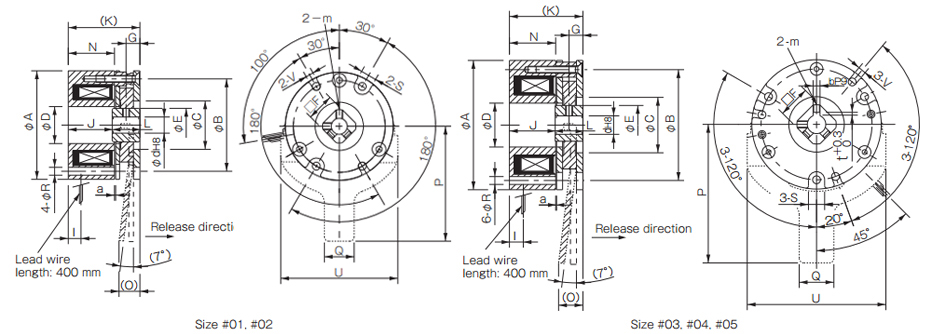
[Dimensions]
単位 [mm]
| Size | Radial direction dimensions | Axial direction dimentions | Bore dimensions |
|---|
| A | B | C | D | E | S | V | R | F | m | O | P | Q | U | G | I | J | K | L | N | a | d | b | t |
|---|
| 01 | 37 | 32 | 18 | 13.5 | 12.0 | 6 | 3 | 3 | 10 | M3 | - | - | - | - | 4.5 | 5.0 | 22.5 | 31.5 | 9 | 22.5 | 0.10 | 5 | - | - |
|---|
| 6 | - | - |
| 02 | 47 | 40 | 21 | 16.0 | 14.5 | 7 | 3.4 | 3.4 | 12 | M3 | 9(10.2) | 50 | 13 | 51 | 6.0 | 5.5 | 19.2 | 31.2 | 12 | 20.0 | 0.10 | 6 | - | - |
|---|
| 7 | - | - |
| 03 | 56 | 48 | 24 | 19.0 | 17.0 | 7 | 3.4 | 3.4 | 14 | M3 | 11(11.7) | 60 | 15 | 60 | 6.0 | 6.0 | 19.9 | 31.9 | 12 | 20.0 | 0.15 | 8 | - | - |
|---|
| 04 | 65 | 58 | 35 | 24.0 | 22.0 | 7 | 3.4 | 3.4 | 18 | M4 | 12(12.5) | 70 | 15 | 70 | 7.0 | 7.0 | 19.9 | 33.9 | 14 | 21.0 | 0.15 | 10 | 3 | 1.2 |
|---|
| 05 | 75 | 66 | 36 | 28.0 | 26.5 | 9 | 4.5 | 4.5 | 22 | M4 | 14(14.5) | 80 | 20 | 80 | 7.0 | 7.0 | 22.1 | 36.1 | 14 | 21.5 | 0.15 | 12 | 4 | 1.5 |
|---|
* There is no release lever option for size #01.
* The dimensions in parentheses ( ) are values for BXW- □ - □ S.
BXW-□-□R Types
[Specifications]
| Model | Size | Static friction torque Ts [N・m] | Coil (at 20℃) | Heat resistance class | Lead wire | Max. rotation speed [min-1] | Rotating part moment of inertia J [kg・m2] | Allowable braking energy rate Ebaℓ [J] | Total braking energy ET [J] | Armature pull-in time ta [s] | Armature release time tar [s] | Mass [kg] |
|---|
| Voltage [V] | Wattage [W] | Current [A] | Resistance [Ω] | UL style | Size |
|---|
| BXW-01-10R | 01 | 0.3 | 24 | 6.1 | 0.254 | 94.4 | F | UL3398 | AWG26 | 6000 | 1.36×10⁻⁷ | 15 | 3000 | 0.035 | 0.020 | 0.1 |
|---|
| BXW-03-10R | 03 | 1.3 | 24 | 7.2 | 0.300 | 80.0 | F | UL3398 | AWG22 | 6000 | 1.17×10⁻⁶ | 87 | 17000 | 0.050 | 0.020 | 0.3 |
|---|
| BXW-05-10R | 05 | 2.5 | 24 | 8.0 | 0.333 | 72.0 | F | UL3398 | AWG22 | 6000 | 3.68×10⁻⁶ | 200 | 40000 | 0.060 | 0.020 | 0.5 |
|---|
*The armature pull-in time and armature release time are taken during DC switching.
[Dimensions]
Unit [mm]
| Size | Radial direction dimensions | Axial direction dimentions | Bore dimensions |
|---|
| A | r | B | C | D | E | S | V | R | F | G | H | I | J | K | L | N | a | d | d max |
|---|
| 01 | 33 | R0.5 | 26.5 | 16 | 9 | 14 | 7 | 3.4 | 32.5 | 12 | 0.2 | 4 | 19 | 25.5~26 | 30 | 4 | 22.8 | 0.1 | 8.5 | 8.5 |
|---|
| 03 | 48 | R1 | 42 | 26 | 14 | 23 | 8 | 3.4 | 47.5 | 19 | 0.2 | 4 | 18 | 25.5~26 | 30 | 4 | 22.6 | 0.1 | 11 | 15 |
|---|
| 05 | 64 | R1 | 56 | 28 | 22 | 31 | 8 | 4.5 | 63.5 | 25 | 0.2 | 4 | 16 | 25~25.5 | 30 | 4.5 | 21.3 | 0.1 | 16 | 20 |
|---|
*Bore diameters other than the standard bore diameters given above are also possible. d max indicates the maximum bore diameter with a round shaft.
*In addition to round bores, key processing can also be handled. Consult Miki Pulley for details.
*Dimensions, mounting and the like are not interchangeable with other BXW models.
Options of BXW Models
Dust Covers
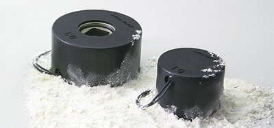
There are dust covers available as optional parts. These dust covers can be used to prevent dust and other foreign particles from entering into the parts, enabling the unit to be used in harsher work environments.
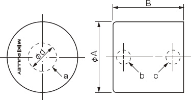
There are two types of dust covers to choose from, one without bores drilled into it for the shaft through-holes that can be used to provide full cover and one with bores drilled into it for the shaft through-holes that can be used with the shaft inserted into the brake. There are also options for the positions of lead wire connecting bores, using either a plate-mounting position or a stator-mounting position for mounting the brake.
[Specifications]
| Material | Ethylene propylene diene monomer (EPDM) rubber |
| Temperature range | -40°C to +140°C |
|---|
| Exterior color | Black |
|---|
| Applicable brake models | L type, H type, S type BXW models |
|---|
| Applicable brake sizes | #01, #02, #03, #04, #05 |
|---|
| Applicable specification voltages | 12 V DC, 24 V DC, 45 V DC, 90 V DC 180 V DC |
|---|
*The temperature range listed is for the dust cover material. The overall operating temperature range for BXW models is from -10°C to +40°C.
*This part cannot be used with BXW models that come with release levers and R type BXW models.
Dimensions
| Type No. |
a |
b |
c |
| 01 |
× |
× |
× |
| 02 |
× |
× |
○ |
| 03 |
× |
○ |
× |
| 04 |
○ |
× |
× |
| 05 |
○ |
× |
○ |
|---|
| 06 |
○ |
○ |
× |
Unit (mm)
| Model |
⌀A |
B |
⌀d |
| BXW-01-C □ |
41 |
33 |
16 |
| BXW-02-C □ |
51 |
33 |
21 |
| BXW-03-C □ |
60 |
33.5 |
24 |
| BXW-04-C □ |
69 |
35.5 |
30 |
| BXW-05-C □ |
79 |
37.5 |
30 |
|---|
*The "a" symbol in the drawings is used to indicate parts with drilled bores for inserting shafts, the "b" symbol for parts with drilled bores for connecting lead wires for mounted plates, and the "c" symbol for parts with drilled bores for connecting lead wires for mounted stators.
*Types no. 01 and 04 will need to have separate bores drilled into them for connecting lead wires.
![]()

 日本語
日本語 English
 Deutsch
 中文
中文 한국어
한국어


