CF-X [O1] Type
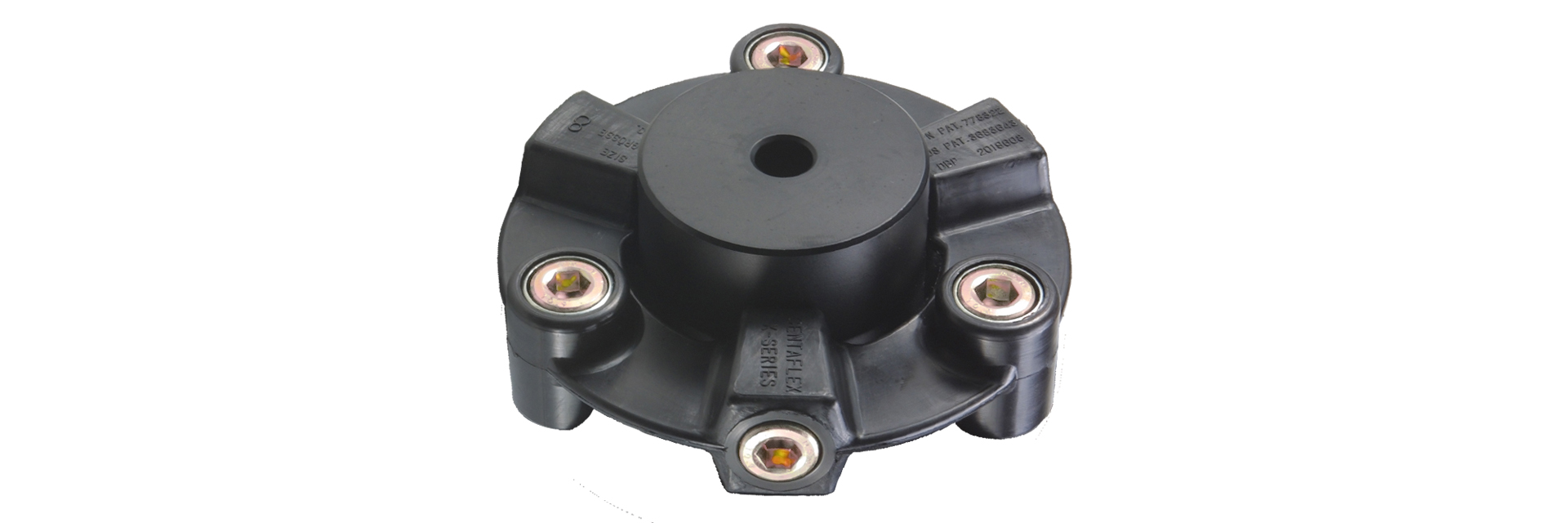
Power is transmitted via a backlash-free design featuring nylon resin elements. This design is rigid in the torsional direction and highly flexible in the lateral and axial directions, enabling precise power transmission while absorbing vibrations and shocks.The O1 type includes a nylon resin element, a cylindrical hub, and mounting bolts.
[Specifications]
| Model | Torque | Tolerance | Maximum Rotational Speed [min⁻¹] |
Static torsional spring constant [N·m/rad] |
Moment of inertia [kg·m²] |
Mass [kg] |
|||
|---|---|---|---|---|---|---|---|---|---|
| Rated [N·m] |
Maximum [N·m] |
Eccentricity [mm] |
Angular offset [°] |
Axial [mm] |
|||||
| CF-X-001-O1 | 15 | 30 | 0.1 | 1 | ±0.5 | 10,000 | 3.0×10³ | 5.25×10⁻⁵ | 0.2 |
| CF-X-002-O1 | 30 | 60 | 0.1 | 1 | ±0.5 | 10,000 | 6.0×10³ | 2.20×10⁻⁴ | 0.4 |
| CF-X-004-O1 | 60 | 120 | 0.1 | 1 | ±0.5 | 8000 | 2.3×10⁴ | 4.83×10⁻⁴ | 0.6 |
| CF-X-008-O1 | 120 | 250 | 0.1 | 1 | ±0.5 | 7000 | 5.8×10⁴ | 1.49×10⁻³ | 1.3 |
| CF-X-016-O1 | 240 | 500 | 0.1 | 1 | ±0.5 | 6000 | 1.1×10⁵ | 3.49×10⁻³ | 2.2 |
| CF-X-025-O1 | 370 | 800 | 0.1 | 1 | ±0.5 | 5000 | 1.7×10⁵ | 7.07×10⁻³ | 3.5 |
[Dimensions]
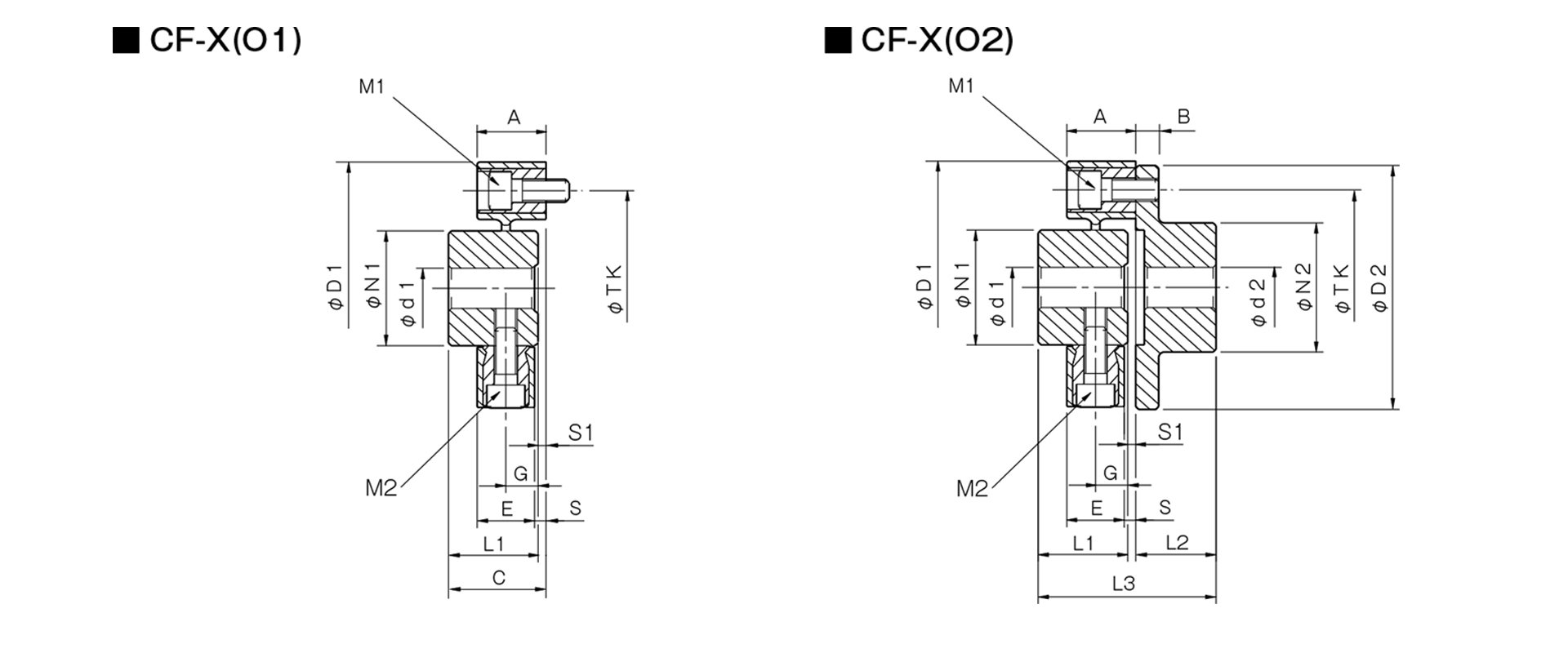
Unit [mm]
| Model | d1 | d2 | D1 | D2 | N1 | N2 | L1 | L2 | L3 | A | B | C | E | G | S | S1 | M1 | M2 | TK | ||||
|---|---|---|---|---|---|---|---|---|---|---|---|---|---|---|---|---|---|---|---|---|---|---|---|
| Pilot hole | Minimum | Max | Pilot hole | Min | Max | ||||||||||||||||||
| CF-X-001 | 8 | 9 | 19 | 8 | 9 | 22 | 57 | 56 | 30 | 36 | 32 | 24 | 57 | 24 | 7 | 33 | 18 | 11 | 3 | 1 | 2-M6 | 2-M6 | 44 |
| CF-X-002 | 10 | 11 | 26 | 9 | 10 | 30 | 88 | 85 | 40 | 45 | 30 | 28 | 62 | 24 | 8 | 34 | 20 | 10 | 4 | 4 | 2-M8 | 2-M8 | 68 |
| CF-X-004 | 12 | 14 | 30 | 11 | 12 | 36 | 100 | 100 | 45 | 55 | 34 | 30 | 66.5 | 25 | 8 | 36.5 | 21 | 12 | 4 | 2.5 | 3-M8 | 3-M8 | 80 |
| CF-X-008 | 12 | 14 | 38 | 15 | 16 | 46 | 125 | 120 | 60 | 70 | 40 | 42 | 85 | 30 | 10 | 43 | 26 | 14 | 4 | 3 | 3-M10 | 3-M10 | 100 |
| CF-X-016 | 15 | 16 | 48 | 19 | 20 | 56 | 155 | 150 | 70 | 85 | 52 | 50 | 105 | 35 | 12 | 55 | 28 | 18 | 7 | 3 | 3-M12 | 3-M12 | 125 |
| CF-X-025 | 15 | 16 | 55 | 19 | 20 | 65 | 175 | 170 | 85 | 100 | 58 | 56 | 117 | 40 | 14 | 61 | 34 | 20 | 6 | 3 | 3-M14 | 3-M14 | 140 |
- The pilot hole is a drill hole. The minimum values for d1 and d2 indicate the minimum hole diameters specified in our standard hole machining specifications, while the maximum values indicate the largest hole diameters that can be machined.
- The designation for M1 and M2 bolts consists of the quantity followed by the thread size.
- The TK dimension refers to the bolt mounting pitch diameter of the flange hub or mating mounting surface.
[Standard Hole Machining Specifications]
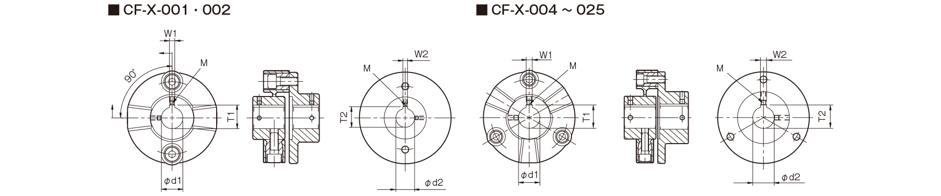
Unit [mm]
| Compliant with JIS B 1301 1959 (Type 2) |
Compliant with New JIS Standard H9 JIS B 1301 1996 |
Motor Standard JIS C 4210 2001 |
||||||||||||
|---|---|---|---|---|---|---|---|---|---|---|---|---|---|---|
| Nominal Bore Diameter | Bore Diameter (d1, d2) |
Keyway width (W1, W2) |
Keyway depth (T1, T2) |
Set screw hole (M) |
Nominal hole diameter | Hole diameter (d1, d2) |
Keyway width (W1, W2) |
Keyway depth (T1, T2) |
Set screw hole (M) |
Nominal hole diameter | Hole diameter (d1, d2) |
Keyway width (W1, W2) |
Keyway depth (T1, T2) |
Set screw hole (M) |
| Nominal hole diameter | Tolerance H7, H8 | Tolerance E9 | - | - | Nominal hole diameter | Tolerance H7 | Tolerance H9 | - | - | Nominal hole diameter | Tolerance G7, F7 | Tolerance H9 | - | - |
| 9 | 9+0.0220 | - | - | 2-M4 | - | - | - | - | - | - | - | - | - | - |
| 10 | 10+0.0220 | - | - | 2-M4 | - | - | - | - | - | - | - | - | - | - |
| 11 | 11 + 0.0180 | - | - | 2-M4 | - | - | - | - | - | - | - | - | - | - |
| 12 | 12 + 0.0180 | 4 + 0.05 + 0.02 | 13.5 + 0.30 | 2-M4 | 12H | 12 + 0.0180 | 4 + 0.030 | 13.8 + 0.30 | 2-M4 | - | - | - | - | - |
| 14 | 14 + 0.0180 | 5 + 0.05 + 0.02 | 16.0 + 0.30 | 2-M4 | 14H | 14 + 0.0180 | 5 + 0.030 | 16.3 + 0.30 | 2-M4 | 14N | 14 + 0.024 + 0.006 | 5 + 0.030 | 16.3 + 0.30 | 2-M4 |
| 15 | 15 + 0.0180 | 5 + 0.05 + 0.02 | 17.0 + 0.30 | 2-M4 | 15H | 15 + 0.0180 | 5 + 0.030 | 17.3 + 0.30 | 2-M4 | - | - | - | - | - |
| 16 | 16 + 0.0180 | 5 + 0.05 + 0.02 | 18.0 + 0.30 | 2-M4 | 16H | 16 + 0.0180 | 5 + 0.030 | 18.3 + 0.30 | 2-M4 | - | - | - | - | - |
| 17 | 17 + 0.0180 | 5 + 0.05 + 0.02 | 19.0 + 0.30 | 2-M4 | 17H | 17 + 0.0180 | 5 + 0.030 | 19.3 + 0.30 | 2-M4 | - | - | - | - | - |
| 18 | 18 + 0.0180 | 5 + 0.05 + 0.02 | 20.0 + 0.30 | 2-M4 | 18H | 18 + 0.0180 | 6 + 0.030 | 20.8 + 0.30 | 2-M5 | - | - | - | - | - |
| 19 | 19 + 0.0210 | 5 + 0.05 + 0.02 | 21.0 + 0.30 | 2-M4 | 19H | 19 + 0.0210 | 6 + 0.030 | 21.8 + 0.30 | 2-M5 | 19N | 19 + 0.028 + 0.007 | 6 + 0.030 | 21.8 + 0.30 | 2-M5 |
| 20 | 20 + 0.0210 | 5 + 0.05 + 0.02 | 22.0 + 0.30 | 2-M4 | 20H | 20 + 0.0210 | 6 + 0.030 | 22.8 + 0.30 | 2-M5 | - | - | - | - | - |
| 22 | 22 + 0.0210 | 7 + 0.061 + 0.025 | 25.0 + 0.30 | 2-M6 | 22H | 22 + 0.0210 | 6 + 0.030 | 24.8 + 0.30 | 2-M5 | - | - | - | - | - |
| 24 | 24 + 0.0210 | 7 + 0.061 + 0.025 | 27.0 + 0.30 | 2-M6 | 24H | 24 + 0.0210 | 8 + 0.0360 | 27.3 + 0.30 | 2-M6 | 24N | 24 + 0.028 + 0.007 | 8 + 0.0360 | 27.3 + 0.30 | 2-M6 |
| 25 | 25 + 0.0210 | 7 + 0.061 + 0.025 | 28.0 + 0.30 | 2-M6 | 25H | 25 + 0.0210 | 8 + 0.0360 | 28.3 + 0.30 | 2-M6 | - | - | - | - | - |
| 28 | 28 + 0.0210 | 7 + 0.061 + 0.025 | 31.0 + 0.30 | 2-M6 | 28H | 28 + 0.0210 | 8 + 0.0360 | 31.3 + 0.30 | 2-M6 | 28N | 28 + 0.02 8 + 0.007 | 8 + 0.0360 | 31.3 + 0.30 | 2-M6 |
| 30 | 30 + 0.0210 | 7 + 0.06 1 + 0.025 | 33.0 + 0.30 | 2-M6 | 30H | 30 + 0.0210 | 8 + 0.0360 | 33.3 + 0.30 | 2-M6 | - | - | - | - | - |
| 32 | 32 + 0.0250 | 10 + 0.06 1 + 0.025 | 35.5 + 0.30 | 2-M8 | 32H | 32 + 0.0250 | 10 + 0.0360 | 35.3 + 0.30 | 2-M8 | - | - | - | - | - |
| 35 | 35 + 0.0250 | 10 + 0.06 1 + 0.025 | 38.5 + 0.30 | 2-M8 | 35H | 35 + 0.0250 | 10 + 0.0360 | 38.3 + 0.30 | 2-M8 | - | - | - | - | - |
| 38 | 38 + 0.0250 | 10 + 0.06 1 + 0.025 | 41.5 + 0.30 | 2-M8 | 38H | 38 + 0.0250 | 10 + 0.0360 | 41.3 + 0.30 | 2-M8 | 38N | 38 + 0.05 + 0.025 | 10 + 0.0360 | 41.3 + 0.30 | 2-M8 |
| 40 | 40 + 0.0250 | 10 + 0.06 1 + 0.025 | 43.5 + 0.30 | 2-M8 | 40H | 40 + 0.0250 | 12 + 0.0430 | 43.3 + 0.30 | 2-M8 | - | - | - | - | - |
| 42 | 42 + 0.0250 | 12 + 0.075 + 0.032 | 45.5 + 0.30 | 2-M8 | 42H | 42 + 0.0250 | 12 + 0.0430 | 45.3 + 0.30 | 2-M8 | 42N | 42 + 0.05 + 0.025 | 12 + 0.0430 | 45.3 + 0.30 | 2-M8 |
| 45 | 45 + 0.0250 | 12 + 0.075 + 0.032 | 48.5 + 0.30 | 2-M8 | 45H | 45 + 0.0250 | 14 + 0.0430 | 48.8 + 0.30 | 2-M10 | - | - | - | - | - |
| 48 | 48 + 0.0250 | 12 + 0.075 + 0.032 | 51.5 + 0.30 | 2-M8 | 48H | 48 + 0.0250 | 14 + 0.0430 | 51.8 + 0.30 | 2-M10 | 48N | 48 + 0.05 + 0.025 | 14 + 0.0430 | 51.8 + 0.30 | 2-M10 |
| 50 | 50 + 0.0250 | 12 + 0.075 + 0.032 | 53.5 + 0.30 | 2-M8 | 50H | 50 + 0.0250 | 14 + 0.0430 | 53.8 + 0.30 | 2-M10 | - | - | - | - | - |
| 55 | 55 + 0.030 | 15 + 0.075 + 0.032 | 60.0 + 0.30 | 2-M10 | 55H | 55 + 0.030 | 16 + 0.0430 | 59.3 + 0.30 | 2-M10 | 55N | 55 + 0.06 + 0.03 | 16 + 0.0430 | 59.3 + 0.30 | 2-M10 |
| 56 | 56 + 0.030 | 15 + 0.075 + 0.032 | 61.0 + 0.30 | 2-M10 | 56H | 56 + 0.030 | 16 + 0.0430 | 60.3 + 0.30 | 2-M10 | - | - | - | - | - |
| 60 | 60 + 0.030 | 15 + 0.075 + 0.032 | 65.0 + 0.30 | 2-M10 | 60H | 60 + 0.030 | 18 + 0.0430 | 64.4 + 0.30 | 2-M10 | 60N | 60 + 0.06 + 0.03 | 18 + 0.0430 | 64.4 + 0.30 | 2-M10 |
| 63 | 63 + 0.030 | 18 + 0.075 + 0.032 | 69.0 + 0.30 | 2-M10 | 63H | 63 + 0.030 | 18 + 0.0430 | 67.4 + 0.30 | 2-M10 | - | - | - | - | - |
| 65 | 65 + 0.030 | 18 + 0.075 + 0.032 | 71.0 + 0.30 | 2-M10 | 65H | 65+0.030 | 18 + 0.0430 | 69.4 + 0.30 | 2-M10 | 65N | 65 + 0.06 + 0.03 | 18 + 0.0430 | 69.4 + 0.30 | 2-M10 |
- All specifications for diameters of 11 mm or less are identical to those listed in the "Old JIS Standards" column.
- The set screw and the keyway will not be on the same plane.
- The set screw is included with the product.
- The positional accuracy of keyway machining is checked visually.
- Please contact us if you require specific positioning accuracy for the keyways relative to each hub.
- For standard dimensions of hole patterns other than those listed here, please refer to the technical documentation.

[Location of the set screw (cylindrical hub)]
| Cylindrical Hub Side Coupling Model | Position from End Face [mm] |
|---|---|
| CF-X-001 | 6 |
| CF-X-002 | 6 |
| CF-X-004 | 6 |
| CF-X-008 | 7 |
| CF-X-016 | 10 |
| CF-X-025 | 10 |