CF-X [OB] Type

This design features a backlash-free structure and power transmission via nylon resin elements. This structure is rigid in the torsional direction yet highly flexible in the lateral and axial directions, enabling precise power transmission while absorbing vibrations and shocks. The OB type includes nylon resin elements and mounting bolts.
[Specifications]
| Model | Torque | Tolerance | Maximum Rotational Speed [min⁻¹] |
Static torsional spring constant [N·m/rad] |
|||||
|---|---|---|---|---|---|---|---|---|---|
| Rated [N·m] |
Maximum [N·m] |
Eccentricity [mm] |
Angular offset [°] |
Axial length [mm] |
Moment of inertia [kg·m²] |
Mass [kg] |
|||
| CF-X-001-OB | 15 | 30 | 0.1 | 1 | ±0.5 | 10,000 | 3.0×10³ | 2.03×10⁻⁵ | 0.04 |
| CF-X-002-OB | 30 | 60 | 0.1 | 1 | ±0.5 | 10,000 | 6.0×10³ | 9.75×10⁻⁵ | 0.1 |
| CF-X-004-OB | 60 | 120 | 0.1 | 1 | ±0.5 | 8000 | 2.3×10⁴ | 2.30×10⁻⁴ | 0.2 |
| CF-X-008-OB | 120 | 250 | 0.1 | 1 | ±0.5 | 7,000 | 5.8×10⁴ | 6.63×10⁻⁴ | 0.3 |
| CF-X-016-OB | 240 | 500 | 0.1 | 1 | ±0.5 | 6000 | 1.1×10⁵ | 1.56×10⁻³ | 0.5 |
| CF-X-025-OB | 370 | 800 | 0.1 | 1 | ±0.5 | 5000 | 1.7×10⁵ | 2.77×10⁻³ | 0.6 |
[Dimensions]
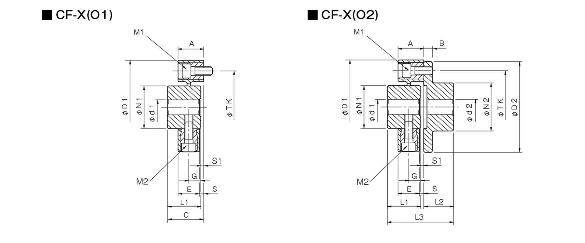
Unit [mm]
| Model | d1 | d2 | D1 | D2 | N1 | N2 | L1 | L2 | L3 | A | B | C | E | G | S | S1 | M1 | M2 | TK | ||||
|---|---|---|---|---|---|---|---|---|---|---|---|---|---|---|---|---|---|---|---|---|---|---|---|
| Pilot hole | Minimum | Max | Pilot hole | Min | Max | ||||||||||||||||||
| CF-X-001 | 8 | 9 | 19 | 8 | 9 | 22 | 57 | 56 | 30 | 36 | 32 | 24 | 57 | 24 | 7 | 33 | 18 | 11 | 3 | 1 | 2-M6 | 2-M6 | 44 |
| CF-X-002 | 10 | 11 | 26 | 9 | 10 | 30 | 88 | 85 | 40 | 45 | 30 | 28 | 62 | 24 | 8 | 34 | 20 | 10 | 4 | 4 | 2-M8 | 2-M8 | 68 |
| CF-X-004 | 12 | 14 | 30 | 11 | 12 | 36 | 100 | 100 | 45 | 55 | 34 | 30 | 66.5 | 25 | 8 | 36.5 | 21 | 12 | 4 | 2.5 | 3-M8 | 3-M8 | 80 |
| CF-X-008 | 12 | 14 | 38 | 15 | 16 | 46 | 125 | 120 | 60 | 70 | 40 | 42 | 85 | 30 | 10 | 43 | 26 | 14 | 4 | 3 | 3-M10 | 3-M10 | 100 |
| CF-X-016 | 15 | 16 | 48 | 19 | 20 | 56 | 155 | 150 | 70 | 85 | 52 | 50 | 105 | 35 | 12 | 55 | 28 | 18 | 7 | 3 | 3-M12 | 3-M12 | 125 |
| CF-X-025 | 15 | 16 | 55 | 19 | 20 | 65 | 175 | 170 | 85 | 100 | 58 | 56 | 117 | 40 | 14 | 61 | 34 | 20 | 6 | 3 | 3-M14 | 3-M14 | 140 |
- The pilot hole is a drill hole. The minimum values for d1 and d2 indicate the minimum hole diameters specified in our standard hole machining specifications, while the maximum values indicate the largest hole diameters that can be machined.
- The designation for M1 and M2 bolts is based on the quantity and thread size.
- The TK dimension refers to the bolt mounting pitch diameter of the flange hub or mating mounting surface.