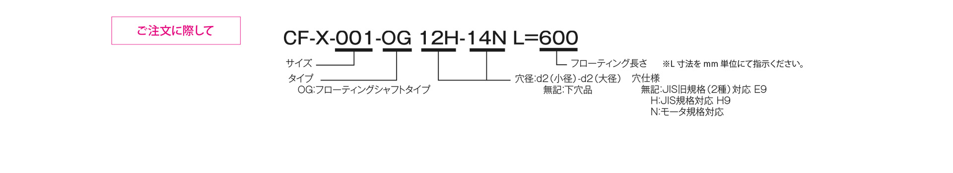
CF-X [OG] Fixed-Length Type
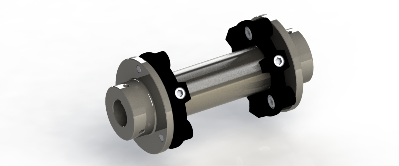
This design features a backlash-free structure and power transmission via nylon resin elements. This structure is rigid in the torsional direction while offering high flexibility in the lateral and axial directions, enabling precise power transmission while absorbing vibrations and shocks.This type features a floating shaft with a customizable overall length, sandwiched between two CF-X models, allowing for a wider tolerance range.
[Specifications]
| Model | Torque | Tolerance | Maximum rotational speed [min⁻¹] | Static torsional spring constant [N·m/rad] | Moment of inertia [kg·m²] | Mass [kg] | Price for pre-drilled holes [JPY] | |||
|---|---|---|---|---|---|---|---|---|---|---|
| Rated torque [N·m] | Maximum [N·m] | Eccentricity [mm] | Angular Deviation [°] | Axial [mm] | ||||||
| CF-X-001-OG | 15 | 30 | 8.2 | 1 | ±0.5 | 2000 | 1.15×10³ | 4.4×10⁻⁴ | 1.2 | |
| CF-X-002-OG | 30 | 60 | 8.2 | 1 | ±0.5 | 2000 | 2.40×10³ | 1.6×10⁻³ | 2.2 | |
| CF-X-004-OG | 60 | 120 | 8.2 | 1 | ±0.5 | 2000 | 6.97×10³ | 3.1×10⁻³ | 3.1 | |
| CF-X-008-OG | 120 | 250 | 8.1 | 1 | ±0.5 | 2000 | 1.75×10⁴ | 8.6×10⁻³ | 5.8 | |
| CF-X-016-OG | 240 | 500 | 7.9 | 1 | ±0.5 | 2000 | 3.15×10⁴ | 2.1×10⁻³ | 9.6 | |
| CF-X-025-OG | 370 | 800 | 7.8 | 1 | ±0.5 | 2000 | 5.76×10⁴ | 4.2×10⁻² | 14.6 | |
- The maximum rotational speed does not take dynamic balance into account.
- The values for the static torsional spring constant are given at 20°C.
- The values for moment of inertia and mass are based on a flange hub with a bottom hole and a length of L=500 mm. (The price remains the same for lengths up to L=600 mm.)
[Dimensions]
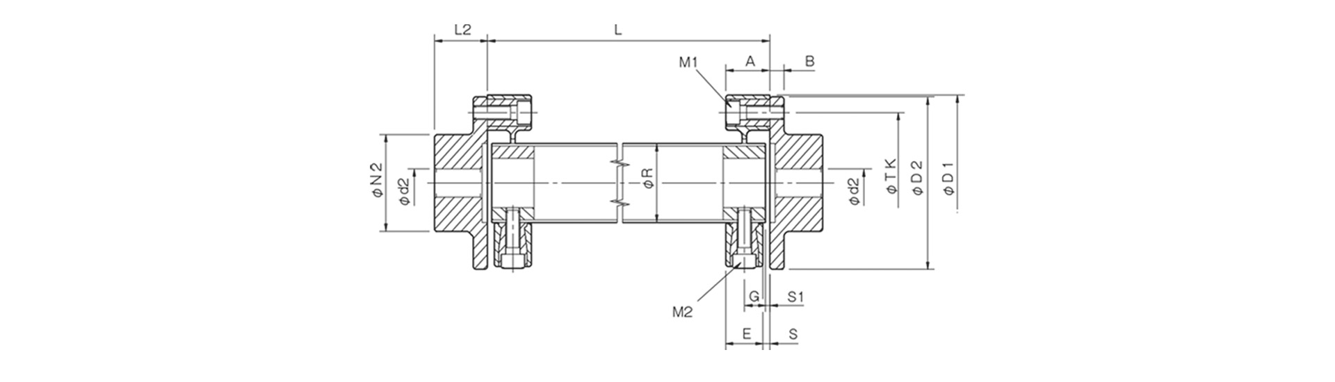
Unit [mm]
| Model | d2 | D1 | D2 | N2 | L2 | A | B | E | G | S | S1 | M1 | M2 | R | TK | ||
|---|---|---|---|---|---|---|---|---|---|---|---|---|---|---|---|---|---|
| Countersink | Minimum | Max | |||||||||||||||
| CF-X-001-OG | 8 | 9 | 22 | 57 | 56 | 36 | 24 | 24 | 7 | 18 | 11 | 3 | 1 | 2-M6 | 2-M6 | 30 | 44 |
| CF-X-002-OG | 9 | 10 | 30 | 88 | 85 | 45 | 28 | 24 | 8 | 20 | 10 | 4 | 4 | 2-M8 | 2-M8 | 40 | 68 |
| CF-X-004-OG | 11 | 12 | 36 | 100 | 100 | 55 | 30 | 25 | 8 | 21 | 12 | 4 | 2.5 | 3-M8 | 3-M8 | 45 | 80 |
| CF-X-008-OG | 15 | 16 | 46 | 125 | 120 | 70 | 42 | 30 | 10 | 26 | 14 | 4 | 3 | 3-M10 | 3-M10 | 60 | 100 |
| CF-X-016-OG | 19 | 20 | 56 | 155 | 150 | 85 | 50 | 35 | 12 | 28 | 18 | 7 | 3 | 3-M12 | 3-M12 | 70 | 125 |
| CF-X-025-OG | 19 | 20 | 65 | 175 | 170 | 100 | 56 | 40 | 14 | 34 | 20 | 6 | 3 | 3-M14 | 3-M14 | 85 | 140 |
- The pilot hole is a drill hole. The minimum values for d1 and d2 indicate the minimum hole diameters specified in our standard hole machining specifications, while the maximum values indicate the largest hole diameters that can be machined.
- The designation for M1 and M2 bolts consists of the quantity followed by the thread size; the quantity refers to the number of bolts on one side.
- The L dimension must be 1000 mm or less. Additionally, the minimum L dimension must allow sufficient space for the installation of an M1 bolt.
[Standard Hole Drilling Specifications]
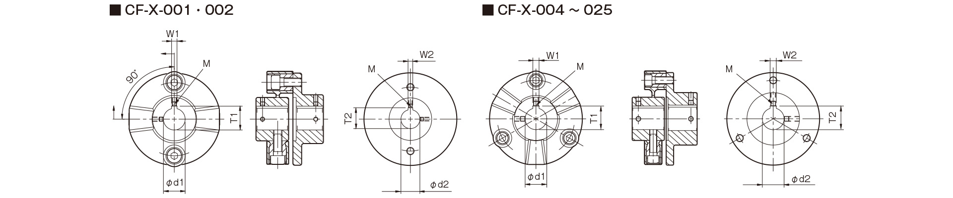
Unit [mm]
| Compliant with JIS B 1301 1959 (Type 2) |
Compliant with New JIS Standard H9 JIS B 1301 1996 |
Motor Standard JIS C 4210 2001 |
||||||||||||
|---|---|---|---|---|---|---|---|---|---|---|---|---|---|---|
| Nominal Bore Diameter | Bore Diameter (d1, d2) |
Keyway width (W1, W2) |
Keyway depth (T1, T2) |
Set screw hole (M) |
Nominal hole diameter | Hole diameter (d1, d2) |
Keyway width (W1, W2) |
Keyway depth (T1, T2) |
Set screw hole (M) |
Nominal hole diameter | Hole diameter (d1, d2) |
Keyway width (W1, W2) |
Keyway depth (T1, T2) |
Set screw hole (M) |
| Nominal hole diameter | Tolerance H7, H8 | Tolerance E9 | - | - | Nominal hole diameter | Tolerance H7 | Tolerance H9 | - | - | Nominal hole diameter | Tolerance G7, F7 | Tolerance H9 | - | - |
| 9 | 9+0.0220 | - | - | 2-M4 | - | - | - | - | - | - | - | - | - | - |
| 10 | 10+0.0220 | - | - | 2-M4 | - | - | - | - | - | - | - | - | - | - |
| 11 | 11 + 0.0180 | - | - | 2-M4 | - | - | - | - | - | - | - | - | - | - |
| 12 | 12 + 0.0180 | 4 + 0.05 + 0.02 | 13.5 + 0.30 | 2-M4 | 12H | 12 + 0.0180 | 4 + 0.030 | 13.8 + 0.30 | 2-M4 | - | - | - | - | - |
| 14 | 14 + 0.0180 | 5 + 0.05 + 0.02 | 16.0 + 0.30 | 2-M4 | 14H | 14 + 0.0180 | 5 + 0.030 | 16.3 + 0.30 | 2-M4 | 14N | 14 + 0.024 + 0.006 | 5 + 0.030 | 16.3 + 0.30 | 2-M4 |
| 15 | 15 + 0.0180 | 5 + 0.05 + 0.02 | 17.0 + 0.30 | 2-M4 | 15H | 15 + 0.0180 | 5 + 0.030 | 17.3 + 0.30 | 2-M4 | - | - | - | - | - |
| 16 | 16 + 0.0180 | 5 + 0.05 + 0.02 | 18.0 + 0.30 | 2-M4 | 16H | 16 + 0.0180 | 5 + 0.030 | 18.3 + 0.30 | 2-M4 | - | - | - | - | - |
| 17 | 17 + 0.0180 | 5 + 0.05 + 0.02 | 19.0 + 0.30 | 2-M4 | 17H | 17 + 0.0180 | 5 + 0.030 | 19.3 + 0.30 | 2-M4 | - | - | - | - | - |
| 18 | 18 + 0.0180 | 5 + 0.05 + 0.02 | 20.0 + 0.30 | 2-M4 | 18H | 18 + 0.0180 | 6 + 0.030 | 20.8 + 0.30 | 2-M5 | - | - | - | - | - |
| 19 | 19 + 0.0210 | 5 + 0.05 + 0.02 | 21.0 + 0.30 | 2-M4 | 19H | 19 + 0.0210 | 6 + 0.030 | 21.8 + 0.30 | 2-M5 | 19N | 19 + 0.028 + 0.007 | 6 + 0.030 | 21.8 + 0.30 | 2-M5 |
| 20 | 20 + 0.0210 | 5 + 0.05 + 0.02 | 22.0 + 0.30 | 2-M4 | 20H | 20 + 0.0210 | 6 + 0.030 | 22.8 + 0.30 | 2-M5 | - | - | - | - | - |
| 22 | 22 + 0.0210 | 7 + 0.061 + 0.025 | 25.0 + 0.30 | 2-M6 | 22H | 22 + 0.0210 | 6 + 0.030 | 24.8 + 0.30 | 2-M5 | - | - | - | - | - |
| 24 | 24 + 0.0210 | 7 + 0.061 + 0.025 | 27.0 + 0.30 | 2-M6 | 24H | 24 + 0.0210 | 8 + 0.0360 | 27.3 + 0.30 | 2-M6 | 24N | 24 + 0.028 + 0.007 | 8 + 0.0360 | 27.3 + 0.30 | 2-M6 |
| 25 | 25 + 0.0210 | 7 + 0.061 + 0.025 | 28.0 + 0.30 | 2-M6 | 25H | 25 + 0.0210 | 8 + 0.0360 | 28.3 + 0.30 | 2-M6 | - | - | - | - | - |
| 28 | 28 + 0.0210 | 7 + 0.061 + 0.025 | 31.0 + 0.30 | 2-M6 | 28H | 28 + 0.0210 | 8 + 0.0360 | 31.3 + 0.30 | 2-M6 | 28N | 28 + 0.02 8 + 0.007 | 8 + 0.0360 | 31.3 + 0.30 | 2-M6 |
| 30 | 30 + 0.0210 | 7 + 0.06 1 + 0.025 | 33.0 + 0.30 | 2-M6 | 30H | 30 + 0.0210 | 8 + 0.0360 | 33.3 + 0.30 | 2-M6 | - | - | - | - | - |
| 32 | 32 + 0.0250 | 10 + 0.06 1 + 0.025 | 35.5 + 0.30 | 2-M8 | 32H | 32 + 0.0250 | 10 + 0.0360 | 35.3 + 0.30 | 2-M8 | - | - | - | - | - |
| 35 | 35 + 0.0250 | 10 + 0.06 1 + 0.025 | 38.5 + 0.30 | 2-M8 | 35H | 35 + 0.0250 | 10 + 0.0360 | 38.3 + 0.30 | 2-M8 | - | - | - | - | - |
| 38 | 38 + 0.0250 | 10 + 0.06 1 + 0.025 | 41.5 + 0.30 | 2-M8 | 38H | 38 + 0.0250 | 10 + 0.0360 | 41.3 + 0.30 | 2-M8 | 38N | 38 + 0.05 + 0.025 | 10 + 0.0360 | 41.3 + 0.30 | 2-M8 |
| 40 | 40 + 0.0250 | 10 + 0.06 1 + 0.025 | 43.5 + 0.30 | 2-M8 | 40H | 40 + 0.0250 | 12 + 0.0430 | 43.3 + 0.30 | 2-M8 | - | - | - | - | - |
| 42 | 42 + 0.0250 | 12 + 0.075 + 0.032 | 45.5 + 0.30 | 2-M8 | 42H | 42 + 0.0250 | 12 + 0.0430 | 45.3 + 0.30 | 2-M8 | 42N | 42 + 0.05 + 0.025 | 12 + 0.0430 | 45.3 + 0.30 | 2-M8 |
| 45 | 45 + 0.0250 | 12 + 0.075 + 0.032 | 48.5 + 0.30 | 2-M8 | 45H | 45 + 0.0250 | 14 + 0.0430 | 48.8 + 0.30 | 2-M10 | - | - | - | - | - |
| 48 | 48 + 0.0250 | 12 + 0.075 + 0.032 | 51.5 + 0.30 | 2-M8 | 48H | 48 + 0.0250 | 14 + 0.0430 | 51.8 + 0.30 | 2-M10 | 48N | 48 + 0.05 + 0.025 | 14 + 0.0430 | 51.8 + 0.30 | 2-M10 |
| 50 | 50 + 0.0250 | 12 + 0.075 + 0.032 | 53.5 + 0.30 | 2-M8 | 50H | 50 + 0.0250 | 14 + 0.0430 | 53.8 + 0.30 | 2-M10 | - | - | - | - | - |
| 55 | 55 + 0.030 | 15 + 0.075 + 0.032 | 60.0 + 0.30 | 2-M10 | 55H | 55 + 0.030 | 16 + 0.0430 | 59.3 + 0.30 | 2-M10 | 55N | 55 + 0.06 + 0.03 | 16 + 0.0430 | 59.3 + 0.30 | 2-M10 |
| 56 | 56 + 0.030 | 15 + 0.075 + 0.032 | 61.0 + 0.30 | 2-M10 | 56H | 56 + 0.030 | 16 + 0.0430 | 60.3 + 0.30 | 2-M10 | - | - | - | - | - |
| 60 | 60 + 0.030 | 15 + 0.075 + 0.032 | 65.0 + 0.30 | 2-M10 | 60H | 60 + 0.030 | 18 + 0.0430 | 64.4 + 0.30 | 2-M10 | 60N | 60 + 0.06 + 0.03 | 18 + 0.0430 | 64.4 + 0.30 | 2-M10 |
| 63 | 63 + 0.030 | 18 + 0.075 + 0.032 | 69.0 + 0.30 | 2-M10 | 63H | 63 + 0.030 | 18 + 0.0430 | 67.4 + 0.30 | 2-M10 | - | - | - | - | - |
| 65 | 65 + 0.030 | 18 + 0.075 + 0.032 | 71.0 + 0.30 | 2-M10 | 65H | 65+0.030 | 18 + 0.0430 | 69.4 + 0.30 | 2-M10 | 65N | 65 + 0.06 + 0.03 | 18 + 0.0430 | 69.4 + 0.30 | 2-M10 |
- All specifications for diameters of 11 mm or less are identical to those listed in the "Old JIS Standards" column.
- The set screw and the keyway will not be on the same plane.
- <br> The set screw is included with the product.
- The positional accuracy of keyway machining is checked visually.
- Please contact us if you require positional accuracy for the keyway relative to each hub.
- For standard dimensions of hole patterns other than those listed here, please refer to the technical documentation.
[Location of the set screw (cylindrical hub)]
Unit [mm]
| Cylindrical Hub Side Coupling Model | Distance from end face [mm] |
|---|---|
| CF-X-001 | 6 |
| CF-X-002 | 6 |
| CF-X-004 | 6 |
| CF-X-008 | 7 |
| CF-X-016 | 10 |
| CF-X-025 | 10 |
[Location of the set screw (flange hub)]
Unit [mm]
| Flange Hub Side Coupling Model | Position from end face [mm] |
|---|---|
| CF-X-001 | 6 |
| CF-X-002 | 7 |
| CF-X-004 | 7 |
| CF-X-008 | 9 |
| CF-X-016 | 10 |
| CF-X-025 | 10 |