CM Models

This engine coupling uses highly elastic rubber to transmit power and excels at absorbing vibrations and shocks. It is extremely flexible in the torsional direction, allowing it to avoid resonance points caused by torsional vibrations at engine speeds below idle. Its short axial length enables easy connection and disconnection of the input and output shafts with just a small axial movement.
[Specifications]
| Model | Rubber hardness 50SH | Rubber Hardness 60SH | Tolerance | Maximum Rotational Speed [min-1] |
Compatible Flange Size SAE J620 |
|||||||
|---|---|---|---|---|---|---|---|---|---|---|---|---|
| Torque | Dynamic torsional spring constant [N·m/rad] |
Torque | Dynamic torsional spring constant [N·m/rad] |
Eccentricity [mm] |
Eccentric angle [°] |
|||||||
| Rated [N·m] |
Maximum [N·m] |
Permissible fluctuation [N·m/10 Hz] |
Rated [N·m] |
Maximum [N·m] |
Permissible fluctuation [N·m/10 Hz] |
|||||||
| CM-800-S1 | 700 | 1400 | 280 | 2.80×10³ | 850 | 1,700 | 340 | 4.20×10³ | 0.5 | 0.5 | 3600 | 10, 11 1/2, 14 |
| CM-1200-S1 | 1000 | 2000 | 400 | 4.50×10³ | 1200 | 2400 | 480 | 7.00×10³ | 0.5 | 0.5 | 3500 | 11 1/2・14 |
| CM-2400-S1 | 2000 | 4000 | 800 | 1.00×10⁴ | 2500 | 5000 | 1000 | 1.50×10⁴ | 0.5 | 0.5 | 3000 | 14 |
| CM-2800-S1 | 2800 | 6000 | 1120 | 2.50×10⁴ | 3000 | 7,500 | 1200 | 3.75×10⁴ | 0.5 | 0.5 | 3000 | 14 |
| CM-3000-S1 | 3000 | 6000 | 1200 | 1.00×10⁴ | 3300 | 7000 | 1,300 | 1.51×10⁴ | 0.5 | 0.5 | 3,000 | 14・18 |
| CM-3500-S1 | 3200 | 6500 | 1280 | 1.60×10⁴ | 3500 | 8000 | 1,400 | 2.40×10⁴ | 0.5 | 0.5 | 3000 | 14–18 |
| CM-4000-S1 | - | - | - | - | 4500 | 11,000 | 1800 | 5.00×10⁴ | 0.5 | 0.5 | 3,000 | 14・18 |
| CM-5000-S1 | 4500 | 9000 | 1800 | 1.70×10⁴ | 5000 | 10,000 | 2,000 | 2.70×10⁴ | 0.5 | 0.5 | 3,000 | 14・18 |
| CM-7000-S1 | 6300 | 12,600 | 2520 | 2.85×10⁴ | 7000 | 14,000 | 2,800 | 4.50×10⁴ | 0.5 | 0.5 | 2,500 | 18 |
| CM-8000-S1 | - | - | - | - | 9000 | 22,000 | 3,600 | 8.00×10⁴ | 0.5 | 0.5 | 2,500 | 18・21 |
| CM-18000-S1 | 16,000 | 32,000 | 6400 | 1.15×10⁵ | 18,000 | 36,000 | 7,200 | 1.70×10⁵ | 0.5 | 0.5 | 2,300 | 21 |
- The maximum rotational speed is based on the smallest flange size. Additionally, dynamic balance has not been taken into account.
[Dimensions]
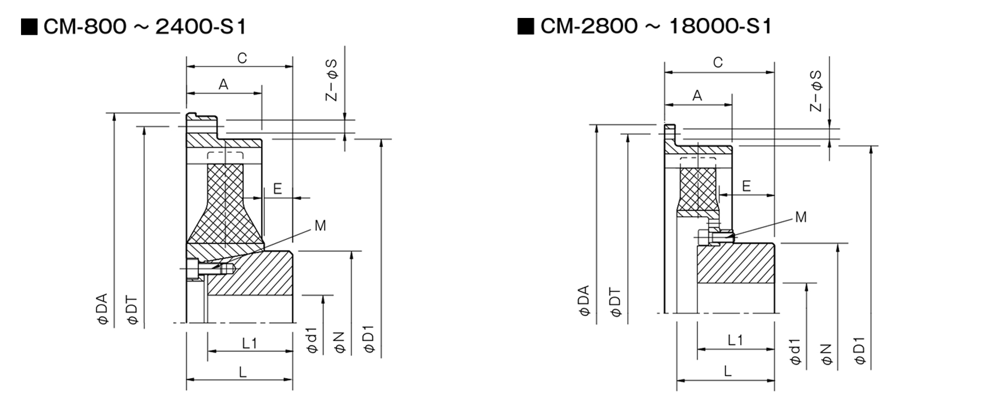
Unit [mm]
| Model | Compatible Flange Size SAE J620 | A | C | d1 | D1 | E | L | L1 | N | M | |
|---|---|---|---|---|---|---|---|---|---|---|---|
| Pilot hole | Max | ||||||||||
| CM-800 | 10 | 50 | 82±2 | 18 | 70 | 316 | 18 | 84 | 66 | 107 | 8-M10 |
| 111/2 | 39 | 71±3 | 18 | 70 | 318 | 18 | 84 | 66 | 107 | 8-M10 | |
| 14 | 46 | 74±6 | 18 | 70 | 318 | 18 | 84 | 66 | 107 | 8-M10 | |
| CM-1200 | 111/2 | 39 | 65±4 | 18 | 70 | 318 | 18 | 84 | 66 | 107 | 8-M10 |
| 14 | 46 | 74±1 | 18 | 70 | 318 | 18 | 84 | 66 | 107 | 8-M10 | |
| CM-2400 | 14 | 61 | 85+8-2 | 28 | 105 | 417 | 16 | 96 | 75 | 150 | 8-M12 |
| CM-2800 | 14 | 61 | 130±4 | 33 | 110 | 417 | 71 | 126 | 100 | 162 | 8-M16 |
| CM-3000 | 14/18 | 70 | 135±8 | 19 | 65 | 465 | 53 | 135 | 105 | 100 | 12-M12 |
| CM-3500 | 14・18 | 70 | 135±6 | 33 | 110 | 465 | 59 | 139 | 100 | 162 | 8-M16 |
| CM-4000 | 14·18 | 70 | 161±6 | 48 | 140 | 465 | 94 | 159 | 125 | 218 | 12-M16 |
| CM-5000 | 14・18 | 70 | 147±2 | 35 | 110 | 465 | 64 | 159 | 105 | 162 | 12-M16 |
| CM-7000 | 18 | 80 | 159±9 | 48 | 140 | 570 | 76 | 161 | 125 | 218 | 12-M16 |
| CM-8000 | 18 | 90 | 197±5 | 68 | 175 | 600 | 110 | 195 | 150 | 248 | 12-M20 |
| 21 | 197±5 | 68 | 584 | 110 | 195 | 150 | 248 | 12-M20 | |||
| CM-18000 | 21 | 141 | 310±9 | 70 | 175 | 680 | 176 | 306 | 200 | 248 | 24-M20 |
| Unit [mm] | |||||
|---|---|---|---|---|---|
| Compatible Flange Nominal Size | 10 | 11 | 14 | 18 | 21 |
| Compatible Flange Size SAE J620 |
10 | 11 1/2 | 14 | 18 | 21 |
| Tue | 314.3 | 352.4 | 466.7 | 571.5 | 673.1 |
| DT | 295.3 | 333.4 | 438.2 | 542.9 | 641.4 |
| Z | 8×45° | 8×45° | 8×45° | 6×60° | 12×30° |
| S | 11 | 11 | 13 | 17 | 17 |
- The drive-side outer ring is dimensioned to mount directly onto an SAE J620 flywheel.