ALS [Y] type
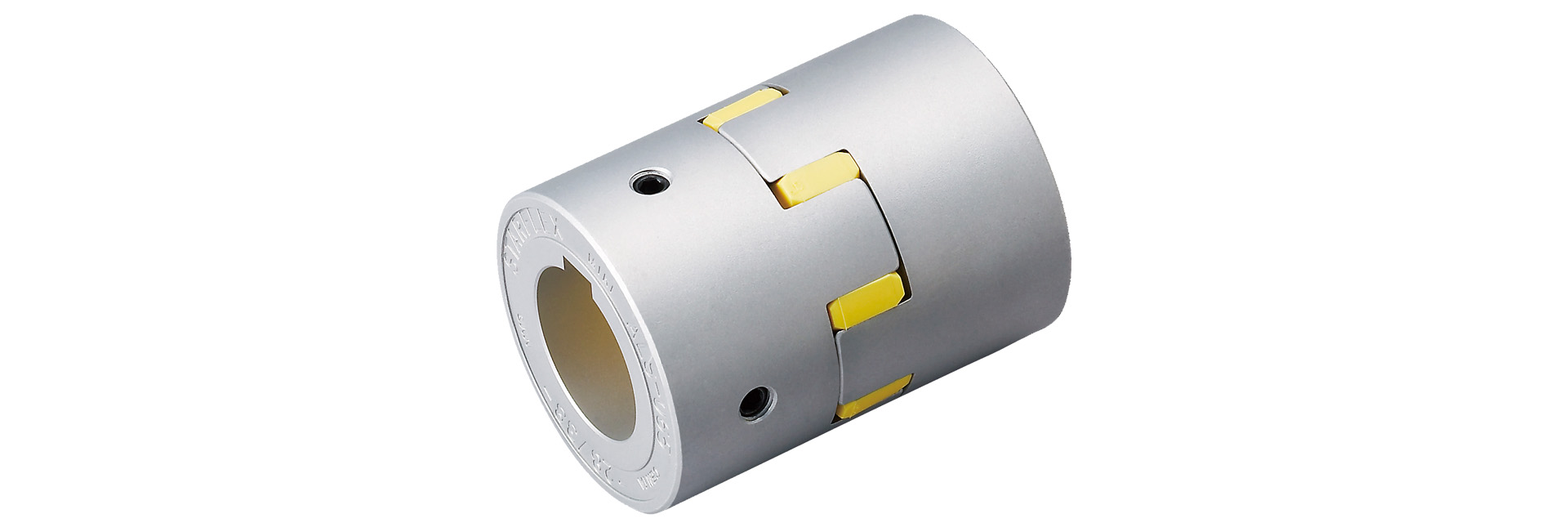
This curved-jaw coupling features a simple design consisting of a cushioning resin (polyurethane elastomer)—referred to as an "element"—sandwiched between two hubs. By using a curved jaw as the power transmission surface, the coupling achieves increased transmission capacity. The element is made of resin with a hardness of 90 JIS A and features a tight-fit design that incorporates pre-compression.
[Specifications] Pilot hole / Key and set screw type
| Model | Torque | Tolerance | Maximum rotational speed [min⁻¹] |
Static torsional spring constant [N·m/rad] |
Radial spring constant [N/mm] |
Moment of inertia [kg·m²] |
Mass [kg] | Standard Drilled Part Price [JPY] | Price for pre-drilled parts [JPY] | |||
|---|---|---|---|---|---|---|---|---|---|---|---|---|
| Working torque : [N·m] |
Maximum [N·m] |
Eccentricity [mm] |
Angular Deviation [°] |
Axial length [mm] |
||||||||
| ALS-014-Y | 1.2 | 2.4 | 0.10 | 1 | 0 to +0.6 | 34,100 | 12 | 200 | 1.91×10⁻⁷ | 0.007 | - | - |
| ALS-020-Y | 3 | 6 | 0.15 | 1 | 0 to +0.8 | 23,800 | 24 | 210 | 1.08×10⁻⁶ | 0.018 | - | - |
| ALS-030-Y | 7.5 | 15 | 0.15 | 1 | 0 to +1.0 | 15,900 | 73 | 330 | 6.25×10⁻⁶ | 0.047 | - | - |
| ALS-040-Y | 10 | 20 | 0.10 | 1 | 0 to +1.2 | 11,900 | 760 | 940 | 3.87×10⁻⁵ | 0.15 | - | - |
| ALS-055-Y | 35 | 70 | 0.15 | 1 | 0 to +1.4 | 8700 | 1400 | 1160 | 1.66×10⁻⁴ | 0.35 | - | - |
| ALS-065-Y | 95 | 190 | 0.15 | 1 | 0 to +1.5 | 7400 | 2100 | 1200 | 3.57×10⁻⁴ | 0.51 | - | - |
| ALS-080-Y | 190 | 380 | 0.15 | 1 | 0 to +1.8 | 6000 | 4000 | 1430 | 1.06×10⁻³ | 1.01 | - | - |
| ALS-095-Y | 265 | 530 | 0.15 | 1 | –0.5 to +2.0 | 5000 | 6000 | 2400 | 2.24×10⁻³ | 1.50 | - | - |
| ALS-105-Y | 310 | 620 | 0.20 | 1 | –0.9 to +2.0 | 4500 | 7000 | 4000 | 3.72×10⁻³ | 2.05 | - | - |
- Axial displacement of the ALS-014 to 018-R models is not permitted in the negative direction.
- The maximum rotational speed does not take dynamic balance into account.
- The values for each spring constant are at 20°C.
- The moment of inertia and mass are based on the maximum bore diameter.
[Dimensions] Pilot hole / Key and set screw type
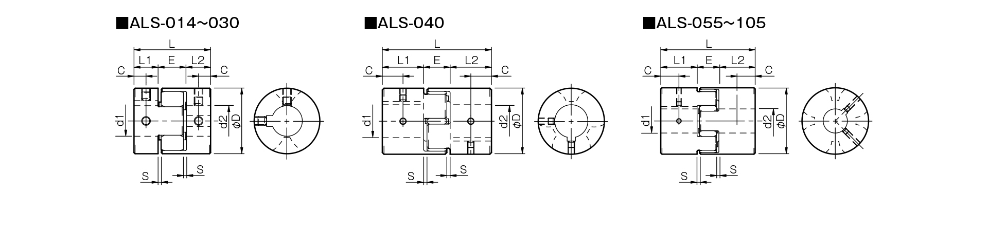
Unit [mm]
| Model | d1・d2 | d1・d4 | D | L | L1・L2 | E | S | C | CAD File No. | |
|---|---|---|---|---|---|---|---|---|---|---|
| Pilot hole | Minimum | Max | ||||||||
| ALS-014-Y | 3 | 3 | 6.5 | 14 | 22 | 7 | 8 | 1 | 3.5 | ALS-HH1 |
| ALS-020-Y | 4 | 4 | 9.6 | 20 | 30 | 10 | 10 | 1 | 5 | ALS-HH2 |
| ALS-030-Y | 5 | 6 | 14 | 30 | 35 | 11 | 13 | 1.5 | 5.5 | ALS-HH3 |
| ALS-040-Y | 5 | 8 | 22 | 40 | 66 | 25 | 16 | 2 | 12.5 | ALS-HH4 |
| ALS-055-Y | 5 | 10 | 28 | 55 | 78 | 30 | 18 | 2 | 15 | ALS-HH5 |
| ALS-065-Y | 5 | 14 | 38 | 65 | 90 | 35 | 20 | 2.5 | 17.5 | ALS-HH6 |
| ALS-080-Y | 10 | 19 | 45 | 80 | 114 | 45 | 24 | 3 | 22.5 | ALS-HH7 |
| ALS-095-Y | 8 | 19 | 55 | 95 | 126 | 50 | 26 | 3 | 25 | - |
| ALS-105-Y | 10 | 19 | 60 | 105 | 140 | 56 | 28 | 3.5 | 28 | - |
- A pilot hole refers to a center hole.
[Standard Hole Diameter]
| Model | Standard hole diameters d1 and d2 [mm] | ||||||||||||||||||||||||||||||||||
|---|---|---|---|---|---|---|---|---|---|---|---|---|---|---|---|---|---|---|---|---|---|---|---|---|---|---|---|---|---|---|---|---|---|---|---|
| 3 | 4 | 5 | 6 | 6.35 | 7 | 8 | 9 | 9.525 | 10 | 11 | 12 | 14 | 15 | 16 | 17 | 18 | 19 | 20 | 22 | 24 | 25 | 28 | 30 | 32 | 35 | 38 | 40 | 42 | 45 | 48 | 50 | 55 | 56 | 60 | |
| ALS-014-Y | ● | ● | ● | ● | ● | ||||||||||||||||||||||||||||||
| ALS-020-Y | ● | ● | ● | ● | ● | ● | ● | ● | |||||||||||||||||||||||||||
| ALS-030-Y | ● | ● | ● | ● | ● | ● | ● | ● | ● | ● | |||||||||||||||||||||||||
| ALS-040-Y | ● | ● | ● | ● | ● | ● | ● | ● | ● | ● | ● | ● | ● | ● | |||||||||||||||||||||
| ALS-055-Y | ● | ● | ● | ● | ● | ● | ● | ● | ● | ● | ● | ● | ● | ● | |||||||||||||||||||||
| ALS-065-Y | ● | ● | ● | ● | ● | ● | ● | ● | ● | ● | ● | ● | ● | ● | ● | ||||||||||||||||||||
| ALS-080-Y | ● | ● | ● | ● | ● | ● | ● | ● | ● | ● | ● | ● | ● | ||||||||||||||||||||||
| ALS-095-Y | ● | ● | ● | ● | ● | ● | ● | ● | ● | ● | ● | ● | ● | ● | ● | ● | |||||||||||||||||||
| ALS-105-Y | ● | ● | ● | ● | ● | ● | ● | ● | ● | ● | ● | ● | ● | ● | ● | ● | ● | ● | |||||||||||||||||
- The hole diameters indicated by the ● symbol and numerical values are standard hole diameters.
- Sizes up to φ11 have no keyway; sizes of φ12 and larger can be machined to accommodate motors compliant with the old JIS standard, the new JIS standard, and the latest standard.

[Standard Hole Specifications] Keyways and Set Screws
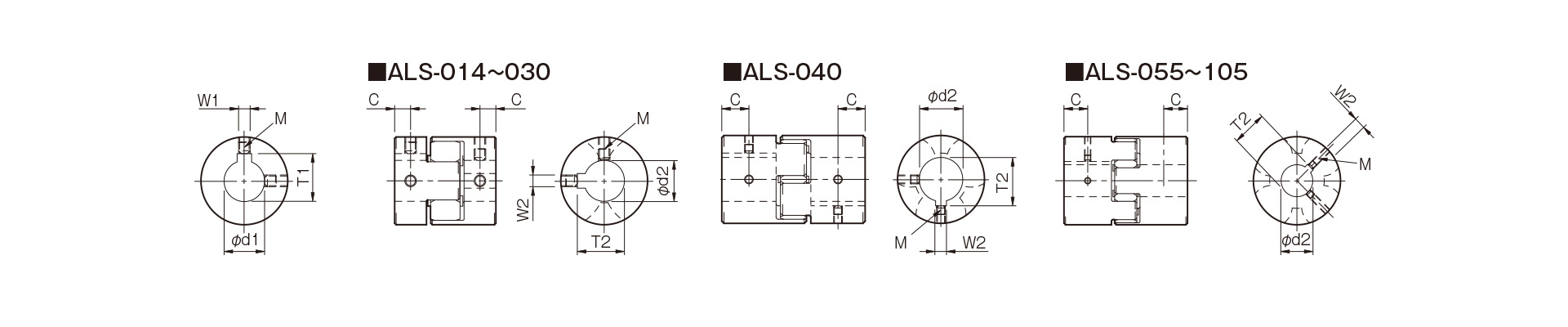
Unit [mm]
| Compliant with JIS B 1301 1959 (Type 2, Old Standard) | New JIS Standard H9 (Compliant with JIS B 1301:1996) | New JIS Standard (Heisei 9) JIS B 1301 1996 | Motor Standard: Compliant with JIS C 4210 2001 | ||||||||||||||||
|---|---|---|---|---|---|---|---|---|---|---|---|---|---|---|---|---|---|---|---|
| Nominal hole diameter | Bore Diameter (d1, d2) |
Keyway width (W1, W2) |
Keyway depth (T1, T2) |
Set screw hole (M) |
Nominal hole diameter | Hole diameter (d1, d2) |
Keyway width (W1, W2) |
Keyway depth (T1, T2) |
Set screw hole (M) |
Nominal hole diameter | Hole diameter (d1, d2) |
Keyway width (W1, W2) |
Keyway depth (T1, T2) |
Set screw hole (M) |
Nominal hole diameter | Hole diameter (d1, d2) |
Keyway width (W1, W2) |
Keyway depth (T1, T2) |
Set screw hole (M) |
| Nominal hole diameter | Tolerance H7, H8 | Tolerance E9 | - | - | Nominal hole diameter | Tolerance H7 | Tolerance H9 | - | - | Nominal hole diameter | Tolerance H7 | Tolerance JS9 | - | - | Nominal hole diameter | Tolerance G7, F7 | Tolerance H9 | - | - |
| 3 | 3+0.0180 | - | - | 1-M3 | - | - | - | ||||||||||||
| 4 | 4+0.0180 | - | - | 2-M3 | - | - | - | ||||||||||||
| 5 | 5 + 0.0180 | - | - | 2-M3 | - | - | - | ||||||||||||
| 6 | 6 + 0.0180 | - | - | 2-M4 | - | - | - | ||||||||||||
| 6.35 | 6.35 + 0.0220 | - | - | 2-M4 | - | - | - | ||||||||||||
| 7 | 7+0.0220 | - | - | 2-M4 | - | - | - | ||||||||||||
| 8 | 8 + 0.0220 | - | - | 2-M4 | - | - | - | ||||||||||||
| 9 | 9 + 0.0220 | - | - | 2-M4 | - | - | - | ||||||||||||
| 9.525 | 9.525 + 0.0220 | - | - | 2-M4 | - | - | - | ||||||||||||
| 10 | 10 + 0.0220 | - | - | 2-M4 | - | - | - | ||||||||||||
| 11 | 11 + 0.0180 | - | - | 2-M4 | - | - | - | ||||||||||||
| 12 | 12 + 0.0180 | 4 + 0.050 + 0.020 | 13.5 + 0.30 | 2-M4 | 12H | 12 + 0.0180 | 4 + 0.0300 | 13.8 + 0.30 | 2-M4 | 12J | 12 + 0.0180 | 4±0.0150 | 13.8 + 0.30 | 2-M4 | - | ||||
| 14 | 14 + 0.0180 | 5 + 0.050 + 0.020 | 16.0 + 0.30 | 2-M4 | 14H | 14 + 0.0180 | 5 + 0.0300 | 16.3 + 0.30 | 2-M4 | 14J | 14 + 0.0180 | 5±0.0150 | 16.3 + 0.30 | 2-M4 | 14N | 14+0.024+0.006 | 5 + 0.0300 | 16.3 + 0.30 | 2-M4 |
| 15 | 15 + 0.0180 | 5 + 0.050 + 0.020 | 17.0 + 0.30 | 2-M4 | 15H | 15 + 0.0180 | 5 + 0.0300 | 17.3 + 0.30 | 2-M4 | 15J | 15 + 0.0180 | 5±0.0150 | 17.3 + 0.30 | 2-M4 | - | ||||
| 16 | 16 + 0.0180 | 5 + 0.050 + 0.020 | 18.0 + 0.30 | 2-M4 | 16H | 16 + 0.0180 | 5 + 0.0300 | 18.3 + 0.30 | 2-M4 | 16J | 16 + 0.0180 | 5±0.0150 | 18.3 + 0.30 | 2-M4 | - | ||||
| 17 | 17 + 0.0180 | 5 + 0.050 + 0.020 | 19.0 + 0.30 | 2-M4 | 17H | 17+0.0180 | 5 + 0.0300 | 19.3 + 0.30 | 2-M4 | 17J | 17 + 0.0180 | 5±0.0150 | 19.3 + 0.30 | 2-M4 | - | ||||
| 18 | 18 + 0.0180 | 5 + 0.050 + 0.020 | 20.0 + 0.30 | 2-M4 | 18H | 18 + 0.0180 | 6 + 0.0300 | 20.8 + 0.30 | 2-M5 | 18J | 18 + 0.0180 | 6±0.0150 | 20.8 + 0.30 | 2-M5 | - | ||||
| 19 | 19 + 0.0210 | 5 + 0.050 + 0.020 | 21.0 + 0.30 | 2-M4 | 19H | 19 + 0.0210 | 6 + 0.0300 | 21.8 + 0.30 | 2-M5 | 19J | 19 + 0.0210 | 6±0.0150 | 21.8 + 0.30 | 2-M5 | 19N | 19+0.028+0.007 | 6 + 0.0300 | 21.8 + 0.30 | 2-M5 |
| 20 | 20 + 0.0210 | 5 + 0.05 0 + 0.020 | 22.0 + 0.30 | 2-M4 | 20H | 20 + 0.0210 | 6 + 0.0300 | 22.8 + 0.30 | 2-M5 | 20J | 20 + 0.0210 | 6±0.0150 | 22.8 + 0.30 | 2-M5 | - | ||||
| 22 | 22 + 0.0210 | 7 + 0.061 + 0.025 | 25.0 + 0.30 | 2-M6 | 22H | 22 + 0.0210 | 6 + 0.0300 | 24.8 + 0.30 | 2-M5 | 22J | 22 + 0.0210 | 6±0.0150 | 24.8 + 0.30 | 2-M5 | - | ||||
| 24 | 24 + 0.0210 | 7 + 0.061 + 0.025 | 27.0 + 0.30 | 2-M6 | 24H | 24 + 0.0210 | 8 + 0.0360 | 27.3 + 0.30 | 2-M6 | 24J | 24 + 0.0210 | 8±0.0180 | 27.3 + 0.30 | 2-M6 | 24N | 24 + 0.028 + 0.007 | 8 + 0.0360 | 27.3 + 0.30 | 2-M6 |
| 25 | 25 + 0.0210 | 7 + 0.061 + 0.025 | 28.0 + 0.30 | 2-M6 | 25H | 25 + 0.0210 | 8 + 0.0360 | 28.3 + 0.30 | 2-M6 | 25J | 25 + 0.0210 | 8±0.0180 | 28.3 + 0.30 | 2-M6 | - | ||||
| 28 | 28 + 0.0210 | 7 + 0.061 + 0.025 | 31.0 + 0.30 | 2-M6 | 28H | 28 + 0.0210 | 8 + 0.0360 | 31.3 + 0.30 | 2-M6 | 28J | 28 + 0.0210 | 8±0.0180 | 31.3 + 0.30 | 2-M6 | 28N | 28 + 0.02 8 + 0.007 | 8 + 0.0360 | 31.3 + 0.30 | 2-M6 |
| 30 | 30 + 0.0210 | 7 + 0.06 1 + 0.025 | 33.0 + 0.30 | 2-M6 | 30H | 30 + 0.0210 | 8 + 0.0360 | 33.3 + 0.30 | 2-M6 | 30J | 30 + 0.0210 | 8±0.0180 | 33.3 + 0.30 | 2-M6 | - | ||||
| 32 | 32 + 0.0250 | 10 + 0.061 + 0.025 | 35.5 + 0.30 | 2-M8 | 32H | 32 + 0.0250 | 10 + 0.0360 | 35.3 + 0.30 | 2-M8 | 32J | 32 + 0.0250 | 10±0.0180 | 35.3 + 0.30 | 2-M8 | - | ||||
| 35 | 35 + 0.0250 | 10 + 0.06 1 + 0.025 | 38.5 + 0.30 | 2-M8 | 35H | 35 + 0.0250 | 10 + 0.0360 | 38.3 + 0.30 | 2-M8 | 35J | 35 + 0.0250 | 10±0.0180 | 38.3 + 0.30 | 2-M8 | - | ||||
| 38 | 38 + 0.0250 | 10 + 0.061 + 0.025 | 41.5 + 0.30 | 2-M8 | 38H | 38 + 0.0250 | 10 + 0.0360 | 41.3 + 0.30 | 2-M8 | 38J | 38 + 0.0250 | 10±0.0180 | 41.3 + 0.30 | 2-M8 | 38N | 38 + 0.050 + 0.025 | 10 + 0.0360 | 41.3 + 0.30 | 2-M8 |
| 40 | 40 + 0.0250 | 10 + 0.06 1 + 0.025 | 43.5 + 0.30 | 2-M8 | 40H | 40 + 0.0250 | 12 + 0.0430 | 43.3 + 0.30 | 2-M8 | 40J | 40 + 0.0250 | 12±0.0215 | 43.3 + 0.30 | 2-M8 | - | ||||
| 42 | 42 + 0.0250 | 12 + 0.075 + 0.032 | 45.5 + 0.30 | 2-M8 | 42H | 42 + 0.0250 | 12 + 0.0430 | 45.3 + 0.30 | 2-M8 | 42J | 42 + 0.0250 | 12±0.0215 | 45.3 + 0.30 | 2-M8 | 42N | 42 + 0.050 + 0.025 | 12 + 0.0430 | 45.3 + 0.30 | 2-M8 |
| 45 | 45 + 0.0250 | 12 + 0.075 + 0.032 | 48.5 + 0.30 | 2-M8 | 45H | 45 + 0.0250 | 14 + 0.0430 | 48.8 + 0.30 | 2-M10 | 45J | 45+0.0250 | 14±0.0215 | 48.8 + 0.30 | 2-M10 | - | ||||
| 48 | 48 + 0.0250 | 12 + 0.075 + 0.032 | 51.5 + 0.30 | 2-M8 | 48H | 48 + 0.0250 | 14 + 0.0430 | 51.8 + 0.30 | 2-M10 | 48J | 48 + 0.0250 | 14±0.0215 | 51.8 + 0.30 | 2-M10 | 48N | 48 + 0.050 + 0.025 | 14 + 0.0430 | 51.8 + 0.30 | 2-M10 |
| 50 | 50 + 0.0250 | 12 + 0.075 + 0.032 | 53.5 + 0.30 | 2-M8 | 50H | 50 + 0.0250 | 14 + 0.0430 | 53.8 + 0.30 | 2-M10 | 50J | 50 + 0.0250 | 14±0.0215 | 53.8 + 0.30 | 2-M10 | - | ||||
| 55 | 55 + 0.0300 | 15 + 0.075 + 0.032 | 60.0 + 0.30 | 2-M10 | 55H | 55 + 0.0300 | 16 + 0.0430 | 59.3 + 0.30 | 2-M10 | 55J | 55 + 0.0300 | 16±0.0215 | 59.3 + 0.30 | 2-M10 | 55N | 55 + 0.060 + 0.030 | 16 + 0.0430 | 59.3 + 0.30 | 2-M10 |
| 56 | 56 + 0.0300 | 15 + 0.075 + 0.032 | 61.0 + 0.30 | 2-M10 | 56H | 56 + 0.0300 | 16 + 0.0430 | 60.3 + 0.30 | 2-M10 | 56J | 56 + 0.0300 | 16±0.0215 | 60.3 + 0.30 | 2-M10 | - | ||||
| 60 | 60 + 0.0300 | 15 + 0.075 + 0.032 | 65.0 + 0.30 | 2-M10 | 60H | 60 + 0.0300 | 18 + 0.0430 | 64.4 + 0.30 | 2-M10 | 60J | 60 + 0.0300 | 18±0.0215 | 64.4 + 0.30 | 2-M10 | 60N | 60 + 0.060 + 0.030 | 18 + 0.0430 | 64.4 + 0.30 | 2-M10 |
- All specifications for diameters of 11 mm or less are identical to those listed in the "Old JIS Standards" column.
- For the ALS-014, the set screw size is M3.
- The set screws are not located on the same plane.
- The set screw is included with the product.
- The positional accuracy of keyway machining is checked visually.
- Please contact us if you require positional accuracy for the keyways relative to each hub.
- For standard dimensions of hole machining other than those listed here, please refer to the technical data at the end of this document.
[Location of the set screw]
Unit [mm]
| Model | Distance from end face [mm] |
|---|---|
| ALS-014 | 3.5 |
| ALS-020 | 5 |
| ALS-030 | 5.5 |
| ALS-040 | 12.5 |
| ALS-055 | 15 |
| ALS-065 | 17.5 |
| ALS-080 | 22.5 |
| ALS-095 | 25 |
| ALS-105 | 28 |
[Specifications] Clamp-type fastening
| Model | Tolerance | Maximum rotational speed [min⁻¹] |
Static torsional spring constant [N·m/rad] |
Radial spring constant [N/mm] |
Moment of inertia [kg·m²] |
Mass [kg] | Price [JPY] | ||
|---|---|---|---|---|---|---|---|---|---|
| Eccentricity [mm] | Angular offset [°] | Axial length [mm] | |||||||
| ALS-014-Y | 0.1 | 1 | 0 to +0.6 | 10,000 | 12 | 200 | 1.98×10⁻⁷ | 0.007 | - |
| ALS-020-Y | 0.15 | 1 | 0 to +0.8 | 10,000 | 24 | 210 | 1.09×10⁻⁶ | 0.019 | - |
| ALS-030-Y | 0.15 | 1 | 0 to +1.0 | 10,000 | 73 | 330 | 6.19×10⁻⁶ | 0.045 | - |
| ALS-040-Y | 0.1 | 1 | 0 to +1.2 | 10,000 | 760 | 940 | 4.01×10⁻⁵ | 0.16 | - |
| ALS-055-Y | 0.15 | 1 | 0 to +1.4 | 7000 | 1400 | 1160 | 1.63×10⁻⁴ | 0.34 | - |
| ALS-065-Y | 0.15 | 1 | 0 to +1.5 | 5900 | 2100 | 1200 | 3.69×10⁻⁴ | 0.54 | - |
| ALS-080-Y | 0.15 | 1 | 0 to +1.8 | 4800 | 4000 | 1430 | 1.04×10⁻³ | 1.00 | - |
- Displacement in the axial direction is not permitted on the negative side.
- The maximum rotational speed does not take dynamic balance into account.
- The values for each spring constant are at 20°C.
- The moment of inertia and mass are based on the maximum bore diameter.
[Dimensions] Clamp-type
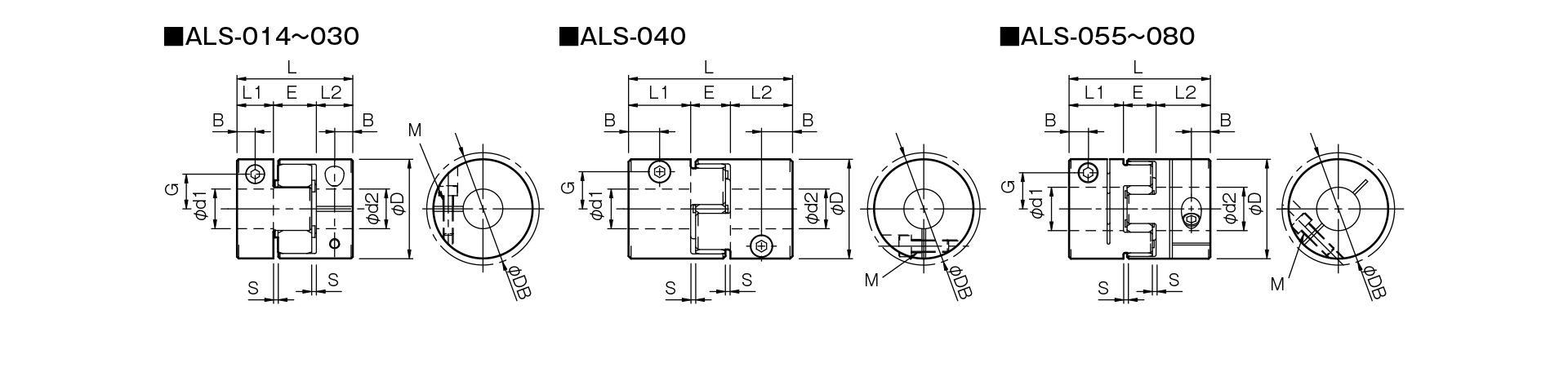
Unit [mm]
| Model | d1・d2 | D | DB | L | L1・L2 | E | S | B | G | M | Tightening torque [N·m] | |
|---|---|---|---|---|---|---|---|---|---|---|---|---|
| Minimum | Max | |||||||||||
| ALS-014-Y | 3 | 6 | 14 | 16.1 | 22 | 7 | 8 | 1 | 3.5 | 4.8 | 1-M2 | 0.4 |
| ALS-020-Y | 4 | 8 | 20 | 20 | 30 | 10 | 10 | 1 | 5 | 6.5 | 1-M2.5 | 1 |
| ALS-030-Y | 6 | 14 | 30 | 30 | 35 | 11 | 13 | 1.5 | 5.5 | 10.5 | 1-M3 | 1.5 |
| ALS-040-Y | 8 | 20 | 40 | 43.2 | 66 | 25 | 16 | 2 | 12.5 | 15 | 1-M5 | 7 |
| ALS-055-Y | 10 | 28 | 55 | 55 | 78 | 30 | 18 | 2 | 10.5 | 20 | 1-M6 | 14 |
| ALS-065-Y | 14 | 35 | 65 | 69.8 | 90 | 35 | 20 | 2.5 | 11.5 | 24.5 | 1-M8 | 30 |
| ALS-080-Y | 19 | 45 | 80 | 80 | 114 | 45 | 24 | 3 | 11.5 | 30 | 1-M8 | 30 |
- The φDB dimension refers to the measurement when the head of the clamping bolt protrudes beyond the outer diameter of the hub.
- The designation for Clamp Bolt M consists of the quantity followed by the thread size; the quantity refers to the number of bolts on one side of the hub.
[Standard Bore Diameter and Allowable Torque]
| Model | Standard Bore Diameters d1 and d2 [mm] and Allowable Transmission Torque [N·m] | ||||||||||||||||||||||||||||
|---|---|---|---|---|---|---|---|---|---|---|---|---|---|---|---|---|---|---|---|---|---|---|---|---|---|---|---|---|---|
| 3 | 4 | 5 | 6 | 6.35 | 7 | 8 | 9 | 9.525 | 10 | 11 | 12 | 14 | 15 | 16 | 18 | 19 | 20 | 22 | 24 | 25 | 28 | 30 | 32 | 35 | 38 | 40 | 42 | 45 | |
| ALS-014-Y | 0.31 | 0.42 | 0.54 | 0.65 | |||||||||||||||||||||||||
| ALS-020-Y | 1.2 | 1.6 | 2.1 | 2.2 | 2.6 | 3 | |||||||||||||||||||||||
| ALS-030-Y | 2 | 2.2 | 2.7 | 3.4 | 4 | 4.4 | 4.7 | 5.4 | 6 | 7.4 | |||||||||||||||||||
| ALS-040-Y | 8 | 12 | 14 | 16 | 19 | 20 | 20 | 20 | 20 | 20 | 20 | 20 | |||||||||||||||||
| ALS-055-Y | 21 | 25 | 28 | 35 | 38 | 41 | 48 | 51 | 54 | 61 | 67 | 70 | 70 | ||||||||||||||||
| ALS-065-Y | 40 | 44 | 47 | 54 | 58 | 61 | 68 | 75 | 79 | 89 | 96 | 103 | 114 | ||||||||||||||||
| ALS-080-Y | 53 | 59 | 72 | 84 | 90 | 108 | 121 | 133 | 151 | 170 | 182 | 194 | 212 | ||||||||||||||||
- The hole diameters listed in the table correspond to standard hole diameters.
- The hole diameter of the field containing the numerical value is limited by the allowable torque, which is determined by the holding force at the shaft fastening section. The numerical value indicates that allowable torque [N·m].
- The dimensional tolerance for the mating shaft is h7. However, for a hole diameter of φ35, the shaft tolerance is +0.010 to -0.025.
- The range of hole diameters we can accommodate is between the minimum and maximum diameters listed in the dimension table. However, we can accommodate hole diameters not listed in the table above; please contact us for more information.

[Element]
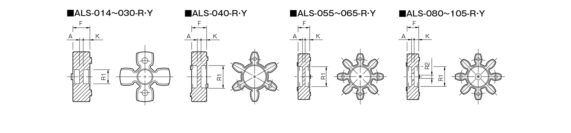
Unit [mm]
| Model | F | R1 | R2 | K | A | Price [JPY] |
|---|---|---|---|---|---|---|
| ALS-014-Y-EL | 6.2 | 3.5 | - | 2.5 | 1.2 | - |
| ALS-020-Y-EL | 8.2 | 6.2 | - | 3.4 | 1.4 | - |
| ALS-030-Y-EL | 10.2 | 8.5 | - | 4 | 2.2 | - |
| ALS-040-Y-EL | 12 | 18 | - | 4.5 | 3 | - |
| ALS-055-Y-EL | 14 | 24 | - | 5.5 | 3 | - |
| ALS-065-Y-EL | 15 | 30 | - | 5.5 | 4 | - |
| ALS-080-Y-EL | 18 | 37 | 15 | 7 | 4 | - |
| ALS-095-Y-EL | 20 | 43 | 20 | 8 | 4 | - |
| ALS-105-Y-EL | 21 | 50 | 20 | 8.5 | 4 | - |