MM[S] Stainless Steel Type
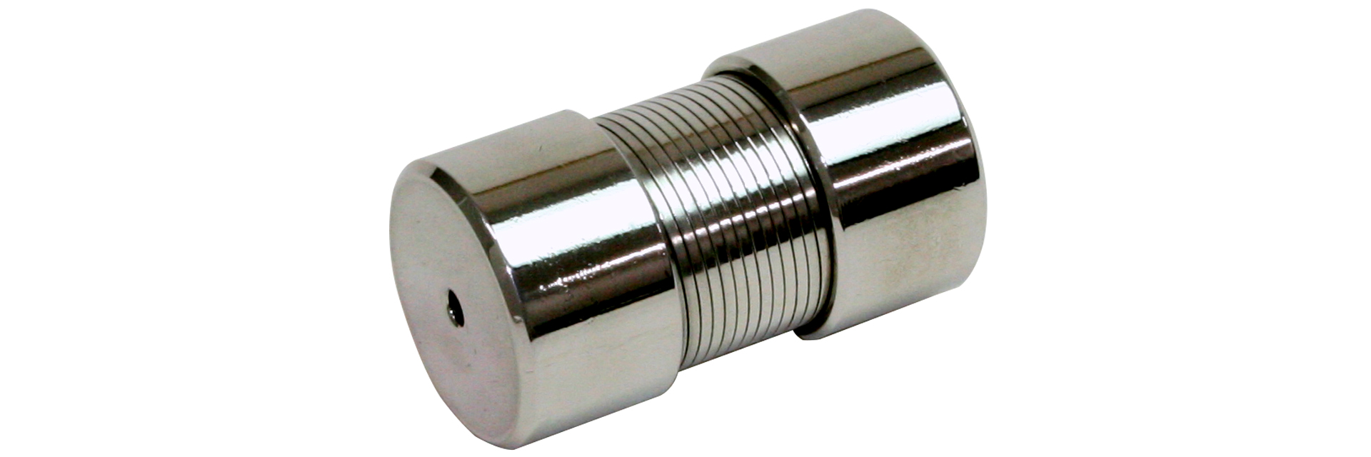
This metal coupling utilizes the elasticity of a spring mechanism and incorporates a metal coil spring. This model offers high flexibility and is capable of accommodating significant misalignments, such as eccentricity and angular misalignment.While the standard model is made of steel, this version features stainless steel hubs and coils for enhanced corrosion resistance.
[Specifications]
| Model | Torque | Tolerance | Maximum rotational speed [min⁻¹] |
Torsional spring constant [N·m/rad] |
Moment of inertia [kg·m²] |
Mass [kg] |
Price of pre-drilled product [JPY] | |||
|---|---|---|---|---|---|---|---|---|---|---|
| Rated torque [N·m] | Maximum [N·m] | Eccentricity [mm] | Angular Deviation [°] | Axial [mm] | ||||||
| MM-6K-S | 2.5 | 5 | 0.3 | 3 | ±0.6 | 20,000 | 143 | 7.65×10⁻⁷ | 0.03 | |
| MM-8K-S | 5 | 10 | 0.3 | 3 | ±0.8 | 15,000 | 286.5 | 4.08×10⁻⁶ | 0.07 | |
| MM-12K-S | 10 | 20 | 0.4 | 3 | ±1.0 | 12,000 | 573 | 1.43×10⁻⁵ | 0.14 | |
| MM-16K-S | 20 | 40 | 0.6 | 3 | ±1.2 | 9000 | 1146 | 6.12×10⁻⁵ | 0.30 | |
| MM-20K-S | 40 | 80 | 0.7 | 3 | ±1.6 | 7,000 | 2292 | 1.99×10⁻⁴ | 0.70 | |
| MM-25K-S | 90 | 180 | 0.9 | 3 | ±2.0 | 6000 | 3438 | 5.66×10⁻⁴ | 1.25 | |
- The maximum rotational speed does not take dynamic balance into account.
- The moment of inertia and mass are based on the maximum bore diameter.
[Dimensions]

| Model | d1・d2 [mm] | D [mm] | L [mm] | L1 [mm] | E [mm] | F [mm] | ||
|---|---|---|---|---|---|---|---|---|
| Pilot hole | Minimum | Max | ||||||
| MM-6K-S | 2.5 | 3 | 8 | 17 | 25 | 9 | 11 | 15.5 |
| MM-8K-S | 3.5 | 4 | 8 | 21 | 35 | 11 | 13 | 19 |
| MM-12K-S | 5.5 | 6 | 12 | 26 | 50 | 16.5 | 16.5 | 24 |
| MM-16K-S | 5.5 | 10 | 16 | 35 | 65 | 22 | 22.4 | 32 |
| MM-20K-S | 5.5 | 10 | 20 | 45 | 80 | 27 | 28 | 40 |
| MM-25K-S | 5.5 | 14 | 25 | 55 | 100 | 33.5 | 35 | 50 |
- The pilot hole will be a drill hole.
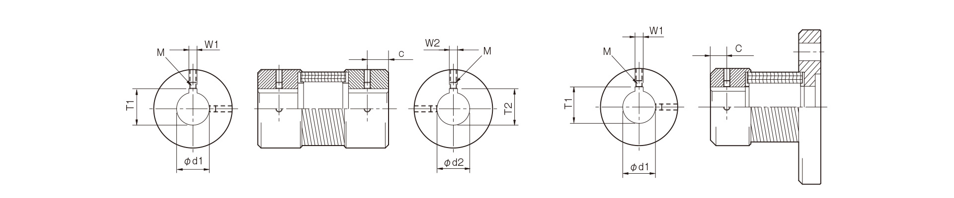
[Standard Hole Drilling Specifications]
Unit [mm]
| Corresponds to JIS B 1301 1959 (Type 2) | New JIS Standard H9 (Compliant with JIS B 1301:1996) | JIS New Standard JS9 (Compliant with JIS B 1301:1996) | Motor Standard: Compliant with JIS C 4210 2001 | ||||||||||||||||
|---|---|---|---|---|---|---|---|---|---|---|---|---|---|---|---|---|---|---|---|
| Nominal hole diameter | Bore Diameter (d1, d2) |
Keyway width (W1, W2) |
Keyway depth (T1, T2) |
Set screw hole (M) |
Nominal hole diameter | Hole diameter (d1, d2) |
Keyway width (W1, W2) |
Keyway depth (T1, T2) |
Set screw hole (M) |
Nominal hole diameter | Hole diameter (d1, d2) |
Keyway width (W1, W2) |
Keyway depth (T1, T2) |
Set screw hole (M) |
Nominal hole diameter | Hole diameter (d1, d2) |
Keyway width (W1, W2) |
Keyway depth (T1, T2) |
Set screw hole (M) |
| Tolerance H7, H8 | Tolerance E9 | - | Tolerance H7 | Tolerance H9 | - | Tolerance H7 | Tolerance JS9 | - | Tolerance G7, F7 | Tolerance H9 | - | ||||||||
| 4 | 4+0.0180 | - | - | 2-M3 | - | - | - | - | - | - | - | - | - | - | - | - | - | - | - |
| 5 | 5+0.0180 | - | - | 2-M3 | - | - | - | - | - | - | - | - | - | - | - | - | - | - | - |
| 6 | 6 + 0.0180 | - | - | 2-M4 | - | - | - | - | - | - | - | - | - | - | - | - | - | - | - |
| 7 | 7 + 0.0220 | - | - | 2-M4 | - | - | - | - | - | - | - | - | - | - | - | - | - | - | - |
| 8 | 8 + 0.0220 | - | - | 2-M4 | - | - | - | - | - | - | - | - | - | - | - | - | - | - | - |
| 9 | 9 + 0.0220 | - | - | 2-M4 | - | - | - | - | - | - | - | - | - | - | - | - | - | - | - |
| 10 | 10 + 0.0220 | - | - | 2-M4 | - | - | - | - | - | - | - | - | - | - | - | - | - | - | - |
| 11 | 11 + 0.0180 | - | - | 2-M4 | - | - | - | - | - | - | - | - | - | - | - | - | - | - | - |
| 12 | 12 + 0.0180 | 4 + 0.05 + 0.02 | 13.5 + 0.30 | 2-M4 | 12H | 12 + 0.0180 | 4 + 0.030 | 13.8 + 0.30 | 2-M4 | 12J | 12 + 0.0180 | 4 + 0.015 – 0.015 | 13.8 + 0.30 | 2-M4 | - | - | - | - | - |
| 14 | 14 + 0.0180 | 5 + 0.05 + 0.02 | 16.0 + 0.30 | 2-M4 | 14H | 14 + 0.0180 | 5 + 0.030 | 16.3 + 0.30 | 2-M4 | 14J | 14 + 0.0180 | 5 + 0.015 – 0.015 | 16.3 + 0.30 | 2-M4 | 14N | 14 + 0.024 + 0.006 | 5 + 0.030 | 16.3 + 0.30 | 2-M4 |
| 15 | 15 + 0.0180 | 5 + 0.05 + 0.02 | 17.0 + 0.30 | 2-M4 | 15H | 15 + 0.0180 | 5 + 0.030 | 17.3 + 0.30 | 2-M4 | 15J | 15 + 0.0180 | 5 + 0.015 – 0.015 | 17.3 + 0.30 | 2-M4 | - | - | - | - | - |
| 16 | 16 + 0.0180 | 5 + 0.05 + 0.02 | 18.0 + 0.30 | 2-M4 | 16H | 16 + 0.0180 | 5 + 0.030 | 18.3 + 0.30 | 2-M4 | 16J | 16 + 0.0180 | 5 + 0.015 – 0.015 | 18.3 + 0.30 | 2-M4 | - | - | - | - | - |
| 17 | 17 + 0.0180 | 5 + 0.05 + 0.02 | 19.0 + 0.30 | 2-M4 | 17H | 17 + 0.0180 | 5 + 0.030 | 19.3 + 0.30 | 2-M4 | 17J | 17 + 0.0180 | 5 + 0.015 – 0.015 | 19.3 + 0.30 | 2-M4 | - | - | - | - | - |
| 18 | 18 + 0.0180 | 5 + 0.05 + 0.02 | 20.0 + 0.30 | 2-M4 | 18H | 18 + 0.0180 | 6 + 0.030 | 20.8 + 0.30 | 2-M5 | 18J | 18 + 0.0180 | 6 + 0.015 – 0.015 | 20.8 + 0.30 | 2-M5 | - | - | - | - | - |
| 19 | 19 + 0.0210 | 5 + 0.05 + 0.02 | 21.0 + 0.30 | 2-M4 | 19H | 19 + 0.0210 | 6 + 0.030 | 21.8 + 0.30 | 2-M5 | 19J | 19 + 0.0210 | 6 + 0.015 – 0.015 | 21.8 + 0.30 | 2-M5 | 19N | 19 + 0.028 + 0.007 | 6 + 0.030 | 21.8 + 0.30 | 2-M5 |
| 20 | 20 + 0.0210 | 5 + 0.05 + 0.02 | 22.0 + 0.30 | 2-M4 | 20H | 20 + 0.0210 | 6 + 0.030 | 22.8 + 0.30 | 2-M5 | 20J | 20 + 0.0210 | 6 + 0.015 – 0.015 | 22.8 + 0.30 | 2-M5 | - | - | - | - | - |
| 22 | 22 + 0.0210 | 7 + 0.061 + 0.025 | 25.0 + 0.30 | 2-M6 | 22H | 22 + 0.0210 | 6 + 0.030 | 24.8 + 0.30 | 2-M5 | 22J | 22 + 0.0210 | 6 + 0.015 – 0.015 | 24.8 + 0.30 | 2-M5 | - | - | - | - | - |
| 24 | 24 + 0.0210 | 7 + 0.061 + 0.025 | 27.0 + 0.30 | 2-M6 | 24H | 24 + 0.0210 | 8 + 0.0360 | 27.3 + 0.30 | 2-M6 | 24J | 24 + 0.0210 | 8 + 0.018 – 0.018 | 27.3 + 0.30 | 2-M6 | 24N | 24 + 0.028 + 0.007 | 8 + 0.0360 | 27.3 + 0.30 | 2-M6 |
| 25 | 25 + 0.0210 | 7 + 0.061 + 0.025 | 28.0 + 0.30 | 2-M6 | 25H | 25 + 0.0210 | 8 + 0.0360 | 28.3 + 0.30 | 2-M6 | 25J | 25 + 0.0210 | 8 + 0.018 – 0.018 | 28.3 + 0.30 | 2-M6 | - | - | - | - | - |
| 28 | 28 + 0.0210 | 7 + 0.061 + 0.025 | 31.0 + 0.30 | 2-M6 | 28H | 28 + 0.0210 | 8 + 0.0360 | 31.3 + 0.30 | 2-M6 | 28J | 28+0.0210 | 8 + 0.018 – 0.018 | 31.3 + 0.30 | 2-M6 | 28N | 28 + 0.028 + 0.007 | 8 + 0.0360 | 31.3 + 0.30 | 2-M6 |
| 30 | 30 + 0.0210 | 7 + 0.06 1 + 0.025 | 33.0 + 0.30 | 2-M6 | 30H | 30 + 0.0210 | 8 + 0.0360 | 33.3 + 0.30 | 2-M6 | 30J | 30 + 0.0210 | 8 + 0.018 – 0.018 | 33.3 + 0.30 | 2-M6 | - | - | - | - | - |
| 32 | 32 + 0.0250 | 10 + 0.061 + 0.025 | 35.5 + 0.30 | 2-M8 | 32H | 32 + 0.0250 | 10 + 0.0360 | 35.3 + 0.30 | 2-M8 | 32J | 32 + 0.0250 | 10 + 0.018 – 0.018 | 35.3 + 0.30 | 2-M8 | - | - | - | - | - |
| 35 | 35 + 0.0250 | 10 + 0.061 + 0.025 | 38.5 + 0.30 | 2-M8 | 35H | 35 + 0.0250 | 10 + 0.0360 | 38.3 + 0.30 | 2-M8 | 35J | 35+0.0250 | 10 + 0.018 – 0.018 | 38.3 + 0.30 | 2-M8 | - | - | - | - | - |
- This standard hole drilling specification applies to Baumannflex MM and MF models.
- All specifications for diameters of 11 mm or less are identical to those listed in the "Old JIS Standards" column.
- The set screws are not located on the same plane.
- The set screw is included with the product.
- The positional accuracy of keyway machining is checked visually.
- Please contact us if you require positional accuracy for the keyways relative to each hub.
- For standard dimensions of hole patterns other than those listed here, please refer to the technical data at the end of this document.

[Location of the set screw]
| Coupling Size | Distance C from end face [mm] |
|---|---|
| 6 | 3 |
| 8 | 5 |
| 12・14 | 7 |
| 16, 19, 20, 24 | 10 |
| 25, 28, 30, 35 | 15 |