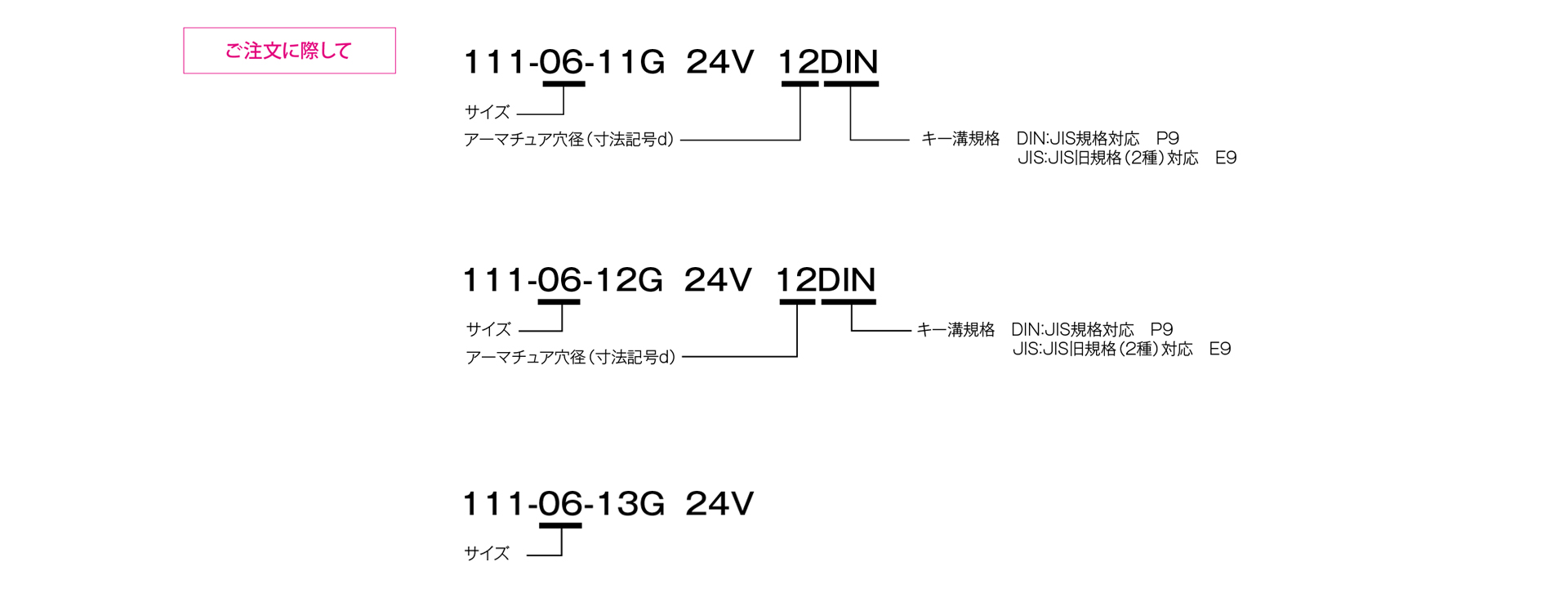
Model 111

This is a standard-size lineup of electromagnetically operated brakes that activate when a current is applied to the coil. These brakes feature a slim design based on the same basic architecture as our clutches. They offer excellent responsiveness and are highly effective for abruptly stopping loads. Three types of armature assemblies with different mounting configurations are available, allowing you to select the one that best suits your needs.
[Specifications]
| Model | Size | Dynamic friction torque Td [N·m] | Static friction torque Ts [N·m] | Coil (at 20°C) | Temperature Rating | Lead wire | Maximum rotational speed [min⁻¹] | Armature moment of inertia J [kg·m²] | Total work until air gap readjustment ET [J] | Armature pull-in time ta [s] | Torque rise time tp [s] | Torque decay time td [s] | Mass [kg] | ||||
|---|---|---|---|---|---|---|---|---|---|---|---|---|---|---|---|---|---|
| Voltage [V] | Power [W] | Current [A] | Resistance [Ω] | UL Style | Size | ||||||||||||
| 111-06-13G | 06 | 5 | 5.5 | DC24 | 11 | 0.46 | 52 | B | UL3398 | AWG 22 | 8000 | 4.23×10⁻⁵ | 36×10⁶ | 0.015 | 0.033 | 0.015 | 0.28 |
| 111-06-12G | 06 | 5 | 5.5 | DC24 | 11 | 0.46 | 52 | B | UL3398 | AWG 22 | 8000 | 6.03×10⁻⁵ | 36×10⁶ | 0.015 | 0.033 | 0.015 | 0.32 |
| 111-06-11G | 06 | 5 | 5.5 | DC24 | 11 | 0.46 | 52 | B | UL3398 | AWG 22 | 8000 | 6.03×10⁻⁵ | 36×10⁶ | 0.015 | 0.033 | 0.015 | 0.32 |
| 111-08-13G | 08 | 10 | 11 | DC24 | 15 | 0.63 | 38 | B | UL3398 | AWG 18 | 6000 | 1.18×10⁻⁴ | 60×10⁶ | 0.016 | 0.042 | 0.025 | 0.5 |
| 111-08-12G | 08 | 10 | 11 | DC24 | 15 | 0.63 | 38 | B | UL3398 | AWG 18 | 6000 | 1.71×10⁻⁴ | 60×10⁶ | 0.016 | 0.042 | 0.025 | 0.58 |
| 111-08-11G | 08 | 10 | 11 | DC24 | 15 | 0.63 | 38 | B | UL3398 | AWG 18 | 6000 | 1.71×10⁻⁴ | 60×10⁶ | 0.016 | 0.042 | 0.025 | 0.58 |
| 111-10-13G | 10 | 20 | 22 | DC24 | 20 | 0.83 | 29 | B | UL3398 | AWG 18 | 5000 | 4.78×10⁻⁴ | 130×10⁶ | 0.018 | 0.056 | 0.030 | 0.91 |
| 111-10-12G | 10 | 20 | 22 | DC24 | 20 | 0.83 | 29 | B | UL3398 | AWG 18 | 5000 | 6.63×10⁻⁴ | 130×10⁶ | 0.018 | 0.056 | 0.030 | 1.07 |
| 111-10-11G | 10 | 20 | 22 | DC24 | 20 | 0.83 | 29 | B | UL3398 | AWG 18 | 5000 | 6.63×10⁻⁴ | 130×10⁶ | 0.018 | 0.056 | 0.030 | 1.07 |
| 111-12-13G | 12 | 40 | 45 | DC24 | 25 | 1.04 | 23 | B | UL3398 | AWG 18 | 4000 | 1.31×10⁻³ | 250×10⁶ | 0.027 | 0.090 | 0.050 | 1.68 |
| 111-12-12G | 12 | 40 | 45 | DC24 | 25 | 1.04 | 23 | B | UL3398 | AWG 18 | 4000 | 1.81×10⁻³ | 250×10⁶ | 0.027 | 0.090 | 0.050 | 1.97 |
| 111-12-11G | 12 | 40 | 45 | DC24 | 25 | 1.04 | 23 | B | UL3398 | AWG 18 | 4000 | 1.81×10⁻³ | 250×10⁶ | 0.027 | 0.090 | 0.050 | 1.97 |
| 111-16-13G | 16 | 80 | 90 | DC24 | 35 | 1.46 | 16 | B | UL3398 | AWG 18 | 3000 | 4.80×10⁻³ | 470×10⁶ | 0.035 | 0.127 | 0.055 | 3.15 |
| 111-16-12G | 16 | 80 | 90 | DC24 | 35 | 1.46 | 16 | B | UL3398 | AWG 18 | 3000 | 6.35×10⁻³ | 470×10⁶ | 0.035 | 0.127 | 0.055 | 3.45 |
| 111-16-11G | 16 | 80 | 90 | DC24 | 35 | 1.46 | 16 | B | UL3398 | AWG 18 | 3000 | 6.35×10⁻³ | 470×10⁶ | 0.035 | 0.127 | 0.055 | 3.45 |
| 111-20-13G | 20 | 160 | 175 | DC24 | 45 | 1.88 | 13 | B | UL3398 | AWG 16 | 2500 | 1.37×10⁻² | 10×10⁸ | 0.065 | 0.200 | 0.070 | 5.9 |
| 111-20-12G | 20 | 160 | 175 | DC24 | 45 | 1.88 | 13 | B | UL3398 | AWG 16 | 2500 | 1.90×10⁻² | 10×10⁸ | 0.065 | 0.200 | 0.070 | 7.1 |
| 111-20-11G | 20 | 160 | 175 | DC24 | 45 | 1.88 | 13 | B | UL3398 | AWG 16 | 2500 | 1.90×10⁻² | 10×10⁸ | 0.065 | 0.200 | 0.070 | 7.1 |
| 111-25-13G | 25 | 320 | 350 | DC24 | 60 | 2.5 | 9.6 | B | UL3398 | AWG 16 | 2000 | 3.58×10⁻² | 20×10⁸ | 0.085 | 0.275 | 0.125 | 10.5 |
| 111-25-12G | 25 | 320 | 350 | DC24 | 60 | 2.5 | 9.6 | B | UL3398 | AWG 16 | 2000 | 4.83×10⁻² | 20×10⁸ | 0.085 | 0.275 | 0.125 | 12.2 |
| 111-25-11G | 25 | 320 | 350 | DC24 | 60 | 2.5 | 9.6 | B | UL3398 | AWG 16 | 2000 | 4.83×10⁻² | 20×10⁸ | 0.085 | 0.275 | 0.125 | 12.2 |
- The dynamic friction torque Td is the value at a relative speed of 100 min⁻¹. Additionally, depending on the initial torque characteristics, a break-in period may be required.
- The moment of inertia and mass of the rotating section are based on the maximum bore diameter.
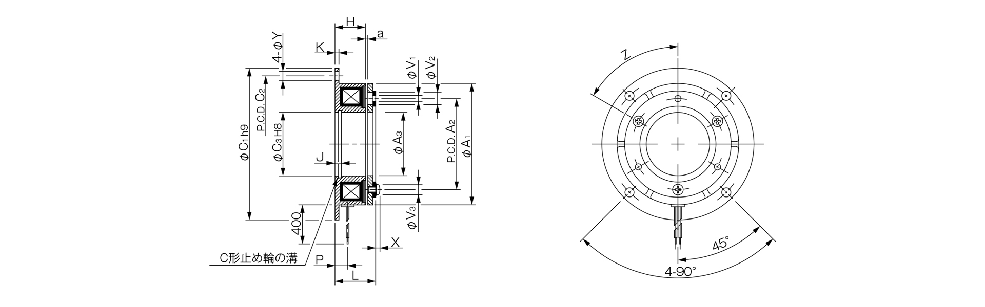
[Dimensions] 111-□-13G
Unit [mm]
| Size | Radial dimensions | Axial dimensions | ||||||||||||||||
|---|---|---|---|---|---|---|---|---|---|---|---|---|---|---|---|---|---|---|
| A1 | A2 | A3 | C1 | C2 | C3 | V1 | V2 | V3 | Y | Z | H | J | K | L | P | X | a | |
| 06 | 63 | 46 | 34.5 | 80 | 72 | 35 | 3–3.1 | 3-6.3 | 3-5.5 | 5 | 6–60° | 18 | 3.5 | 2.1 | 22 | 7.3 | 2.5 | 0.2–±0.05 |
| 08 | 80 | 60 | 41.7 | 100 | 90 | 42 | 3-4.1 | 3-8 | 3-7 | 6 | 6–60° | 20 | 4.3 | 2.6 | 24.5 | 8.3 | 2.85 | 0.2–±0.05 |
| 10 | 100 | 76 | 51.5 | 125 | 112 | 52 | 3-5.1 | 3-11 | 3-9 | 7 | 6–60° | 22 | 5 | 3.1 | 28.1 | 9 | 3.3 | 0.2 to ±0.05 |
| 12 | 125 | 95 | 61.5 | 150 | 137 | 62 | 3-6.1 | 3-12 | 3-11 | 7 | 6–60° | 24 | 5.5 | 3.6 | 31 | 9.3 | 3.3 | 0.3 + 0.05 - 0.1 |
| 16 | 160 | 120 | 79.5 | 190 | 175 | 80 | 3–8.2 | 3-15 | 3-14 | 9.5 | 6–60° | 26 | 6 | 4.1 | 35 | 11.7 | 3.5 | 0.3 + 0.05 - 0.1 |
| 20 | 200 | 158 | 99.5 | 230 | 215 | 100 | 3-10.2 | 3-18 | 3-16.2 | 9.5 | 6–60° | 30 | 7 | 5.1 | 41.4 | 13.4 | 4.9 | 0.50–0.2 |
| 25 | 250 | 210 | 124.5 | 290 | 270 | 125 | 4-12.2 | 4-22 | 4-20 | 11.5 | 8–45° | 35 | 8 | 6.1 | 47.9 | 16 | 5.5 | 0.50–0.2 |
- For information regarding installation methods, please refer to the design specifications.
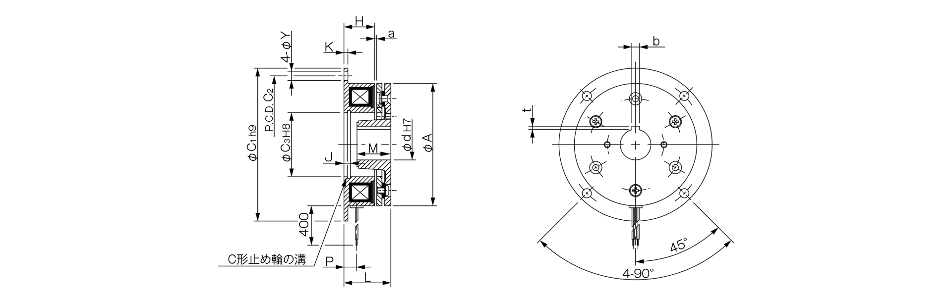
[Dimensions] 111-□-12G
Unit [mm]
| Size | Radial dimensions | Axial dimensions | ||||||||||
|---|---|---|---|---|---|---|---|---|---|---|---|---|
| A | C1 | C2 | C3 | Y | H | J | K | L | M | P | a | |
| 06 | 63 | 80 | 72 | 35 | 5 | 18 | 3.5 | 2.1 | 25.5 | 15 | 7.3 | 0.2–±0.05 |
| 08 | 80 | 100 | 90 | 42 | 6 | 20 | 4.3 | 2.6 | 28.5 | 20 | 8.3 | 0.2 to ±0.05 |
| 10 | 100 | 125 | 112 | 52 | 7 | 22 | 5 | 3.1 | 33.1 | 25 | 9 | 0.2–±0.05 |
| 12 | 125 | 150 | 137 | 62 | 7 | 24 | 5.5 | 3.6 | 37 | 30 | 9.3 | 0.3 + 0.05 - 0.1 |
| 16 | 160 | 190 | 175 | 80 | 9.5 | 26 | 6 | 4.1 | 42 | 38 | 11.7 | 0.3 + 0.05 - 0.1 |
| 20 | 200 | 230 | 215 | 100 | 9.5 | 30 | 7 | 5.1 | 50.4 | 45 | 13.4 | 0.50–0.2 |
| 25 | 250 | 290 | 270 | 125 | 11.5 | 35 | 8 | 6.1 | 58.9 | 54 | 16 | 0.50–0.2 |
Unit [mm]
| Size | Shaft Bore Dimensions | ||||
|---|---|---|---|---|---|
| d H7 | Compliant with JIS standards | Compliant with Old JIS Standards | |||
| d H7 | b P9 | t | b P9 | t | |
| 06 | 12 | 4–0.012–0.042 | 1.5 + 0.50 | 4 + 0.050 + 0.020 | 1.5 + 0.50 |
| 15 | 5–0.012–0.042 | 2 + 0.50 | 5 + 0.050 + 0.020 | 2 + 0.50 | |
| 08 | 15 | 5–0.012–0.042 | 2 + 0.50 | 5 + 0.050 + 0.020 | 2 + 0.50 |
| 20 | 6–0.012–0.042 | 2.5 + 0.50 | 5 + 0.050 + 0.020 | 2 + 0.50 | |
| 10 | 20 | 6–0.012–0.042 | 2.5 + 0.50 | 5 + 0.050 + 0.020 | 2 + 0.50 |
| 25 | 8–0.015–0.051 | 3 + 0.50 | 7 + 0.061 + 0.025 | 3 + 0.50 | |
| 12 | 25 | 8–0.015–0.051 | 3 + 0.50 | 7 + 0.061 + 0.025 | 3 + 0.50 |
| 30 | 8–0.015–0.051 | 3 + 0.50 | 7 + 0.061 + 0.025 | 3 + 0.50 | |
| 16 | 30 | 8–0.015–0.051 | 3 + 0.50 | 7 + 0.061 + 0.025 | 3 + 0.50 |
| 40 | 12–0.018–0.061 | 3 + 0.50 | 10 + 0.061 + 0.025 | 3.5 + 0.50 | |
| 20 | 40 | 12–0.018–0.061 | 3 + 0.50 | 10 + 0.061 + 0.025 | 3.5 + 0.50 |
| 50 | 14–0.018–0.061 | 3.5 + 0.50 | 12 + 0.075 + 0.032 | 3.5 + 0.50 | |
| 25 | 50 | 14–0.018–0.061 | 3.5 + 0.50 | 12 + 0.075 + 0.032 | 3.5 + 0.50 |
| 60 | 18–0.018–0.061 | 4 + 0.50 | 15 + 0.075 + 0.032 | 5 + 0.50 | |
- For information regarding installation methods, please refer to the design specifications.
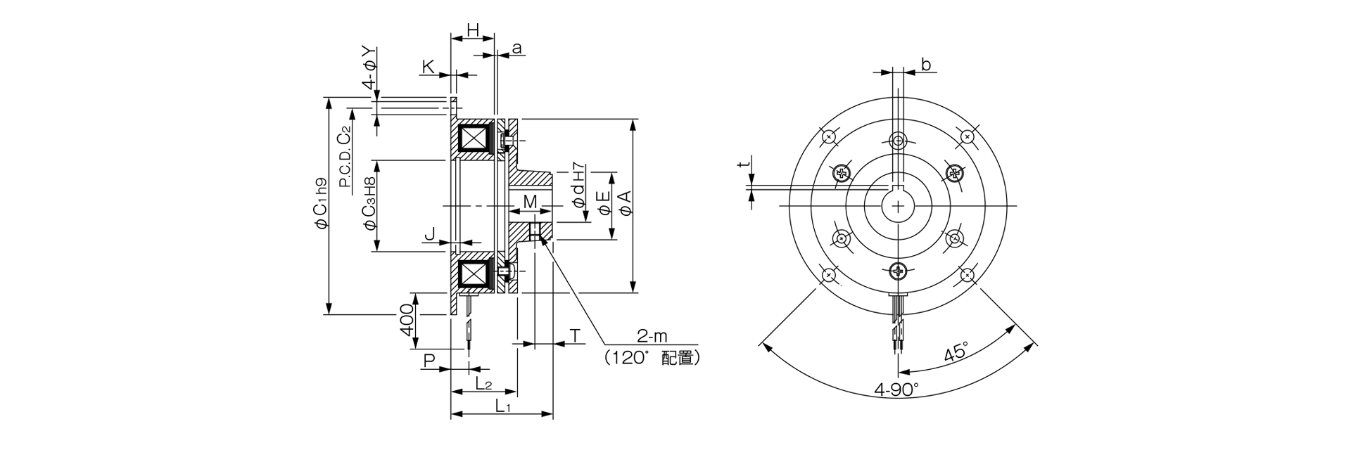
[Dimensions] 111-□-11G
Unit [mm]
| Size | Radial dimensions | Axial dimensions | ||||||||||||||
|---|---|---|---|---|---|---|---|---|---|---|---|---|---|---|---|---|
| A | C1 | C2 | C3 | E | Y | m | H | J | K | L1 | L2 | M | P | T | a | |
| 06 | 63 | 80 | 72 | 35 | 26 | 5 | M4 | 18 | 3.5 | 2.1 | 37 | 25.5 | 15 | 7.3 | 6 | 0.2–±0.05 |
| 08 | 80 | 100 | 90 | 42 | 31 | 6 | M5 | 20 | 4.3 | 2.6 | 44.5 | 28.5 | 20 | 8.3 | 8 | 0.2–±0.05 |
| 10 | 100 | 125 | 112 | 52 | 41 | 7 | M5 | 22 | 5 | 3.1 | 53.1 | 33.1 | 25 | 9 | 10 | 0.2–±0.05 |
| 12 | 125 | 150 | 137 | 62 | 49 | 7 | M6 | 24 | 5.5 | 3.6 | 61 | 37 | 30 | 9.3 | 12 | 0.3 + 0.05 - 0.1 |
| 16 | 160 | 190 | 175 | 80 | 65 | 9.5 | M8 | 26 | 6 | 4.1 | 73 | 42 | 38 | 11.7 | 15 | 0.3 + 0.05 - 0.1 |
| 20 | 200 | 230 | 215 | 100 | 83 | 9.5 | M8 | 30 | 7 | 5.1 | 86.4 | 50.4 | 45 | 13.4 | 18 | 0.50–0.2 |
| 25 | 250 | 290 | 270 | 125 | 105 | 11.5 | M10 | 35 | 8 | 6.1 | 101.9 | 58.9 | 54 | 16 | 22 | 0.50–0.2 |
Unit [mm]
| Size | Shaft Bore Dimensions | ||||
|---|---|---|---|---|---|
| d H7 | Compliant with JIS standards | Compliant with Old JIS Standards | |||
| d H7 | b P9 | t | b P9 | t | |
| 06 | 12 | 4–0.012–0.042 | 1.5 + 0.50 | 4 + 0.050 + 0.020 | 1.5 + 0.50 |
| 15 | 5–0.012–0.042 | 2 + 0.50 | 5 + 0.050 + 0.020 | 2 + 0.50 | |
| 08 | 15 | 5–0.012–0.042 | 2 + 0.50 | 5 + 0.050 + 0.020 | 2 + 0.50 |
| 20 | 6–0.012–0.042 | 2.5 + 0.50 | 5 + 0.050 + 0.020 | 2 + 0.50 | |
| 10 | 20 | 6–0.012–0.042 | 2.5 + 0.50 | 5 + 0.050 + 0.020 | 2 + 0.50 |
| 25 | 8–0.015–0.051 | 3 + 0.50 | 7 + 0.061 + 0.025 | 3 + 0.50 | |
| 12 | 25 | 8–0.015–0.051 | 3 + 0.50 | 7 + 0.061 + 0.025 | 3 + 0.50 |
| 30 | 8–0.015–0.051 | 3 + 0.50 | 7 + 0.061 + 0.025 | 3 + 0.50 | |
| 16 | 30 | 8 - 0.015 - 0.051 | 3 + 0.50 | 7 + 0.061 + 0.025 | 3 + 0.50 |
| 40 | 12–0.018–0.061 | 3 + 0.50 | 10 + 0.061 + 0.025 | 3.5 + 0.50 | |
| 20 | 40 | 12–0.018–0.061 | 3 + 0.50 | 10 + 0.061 + 0.025 | 3.5 + 0.50 |
| 50 | 14–0.018–0.061 | 3.5 + 0.50 | 12 + 0.075 + 0.032 | 3.5 + 0.50 | |
| 25 | 50 | 14–0.018–0.061 | 3.5 + 0.50 | 12 + 0.075 + 0.032 | 3.5 + 0.50 |
| 60 | 18–0.018–0.061 | 4 + 0.50 | 15 + 0.075 + 0.032 | 5 + 0.50 | |
- For information regarding installation methods, please refer to the design specifications.