Model 112

This is a compact line of micro-sized electromagnetically operated brakes that activate when an electric current is applied to the coil. These high-performance, compact brakes share the same basic design as small clutches. Three types of armature assemblies with different mounting configurations are available, allowing you to select the one that best suits your needs.
[Specifications]
| Model | Size | Dynamic friction torque Td [N·m] | Coil (at 20°C) | Temperature Rating | Lead Wire | Maximum rotational speed [min⁻¹] | Armature moment of inertia J [kg·m²] | Permissible braking work Ebaℓ [J] | Total work until air gap readjustment ET [J] | Armature deceleration time ta [s] | Torque rise time tp [s] | Torque decay time td [s] | Mass [kg] | ||||
|---|---|---|---|---|---|---|---|---|---|---|---|---|---|---|---|---|---|
| Voltage [V] | Power [W] | Current [A] | Resistance [Ω] | UL Style | Size | ||||||||||||
| 112-02-13 | 2 | 0.4 | DC24 | 6 | 0.25 | 96 | B | UL3398 | AWG 26 | 10,000 | 6.75×10⁻⁷ | 1500 | 2×10⁶ | 0.004 | 0.01 | 0.01 | 0.053 |
| February 12, 2011 | 2 | 0.4 | DC24 | 6 | 0.25 | 96 | B | UL3398 | AWG 26 | 10,000 | 1.00×10⁻⁶ | 1500 | 2×10⁶ | 0.004 | 0.01 | 0.01 | 0.057 |
| February 11, 2011 | 2 | 0.4 | DC24 | 6 | 0.25 | 96 | B | UL3398 | AWG 26 | 10,000 | 1.00×10⁻⁶ | 1500 | 2×10⁶ | 0.004 | 0.01 | 0.01 | 0.057 |
| March 13, 2011 | 3 | 0.6 | DC24 | 6 | 0.25 | 96 | B | UL3398 | AWG 26 | 10,000 | 1.30×10⁻⁶ | 2300 | 3×10⁶ | 0.005 | 0.012 | 0.008 | 0.072 |
| March 12, 2011 | 3 | 0.6 | DC24 | 6 | 0.25 | 96 | B | UL3398 | AWG 26 | 10,000 | 1.95×10⁻⁶ | 2300 | 3×10⁶ | 0.005 | 0.012 | 0.008 | 0.079 |
| March 11, 2011 | 3 | 0.6 | DC24 | 6 | 0.25 | 96 | B | UL3398 | AWG 26 | 10,000 | 1.95×10⁻⁶ | 2300 | 3×10⁶ | 0.005 | 0.012 | 0.008 | 0.079 |
| April 13, 2011 | 4 | 1.2 | DC24 | 8 | 0.33 | 72 | B | UL3398 | AWG 26 | 10,000 | 4.38×10⁻⁶ | 4500 | 6×10⁶ | 0.007 | 0.016 | 0.01 | 0.118 |
| April 12, 2011 | 4 | 1.2 | DC24 | 8 | 0.33 | 72 | B | UL3398 | AWG 26 | 10,000 | 6.15×10⁻⁶ | 4500 | 6×10⁶ | 0.007 | 0.016 | 0.01 | 0.131 |
| April 11, 2011 | 4 | 1.2 | DC24 | 8 | 0.33 | 72 | B | UL3398 | AWG 26 | 10,000 | 6.15×10⁻⁶ | 4500 | 6×10⁶ | 0.007 | 0.016 | 0.01 | 0.131 |
| May 13, 2011 | 5 | 2.4 | DC24 | 10 | 0.42 | 58 | B | UL3398 | AWG22 | 10,000 | 9.08×10⁻⁶ | 9000 | 9×10⁶ | 0.01 | 0.023 | 0.012 | 0.2 |
| May 12, 2011 | 5 | 2.4 | DC24 | 10 | 0.42 | 58 | B | UL3398 | AWG22 | 10,000 | 1.38×10⁻⁵ | 9000 | 9×10⁶ | 0.01 | 0.023 | 0.012 | 0.215 |
| May 11, 2011 | 5 | 2.4 | DC24 | 10 | 0.42 | 58 | B | UL3398 | AWG22 | 10,000 | 1.38×10⁻⁵ | 9000 | 9×10⁶ | 0.01 | 0.023 | 0.012 | 0.215 |
- The dynamic friction torque Td is the value at a relative speed of 100 min⁻¹. Additionally, depending on the initial torque characteristics, a break-in period may be required.
- Keep fluctuations in the supply voltage within ±10% of the coil voltage. Also, ensure that the duty cycle does not exceed 80%.
- The moment of inertia and mass of the rotating section are based on the maximum bore diameter.
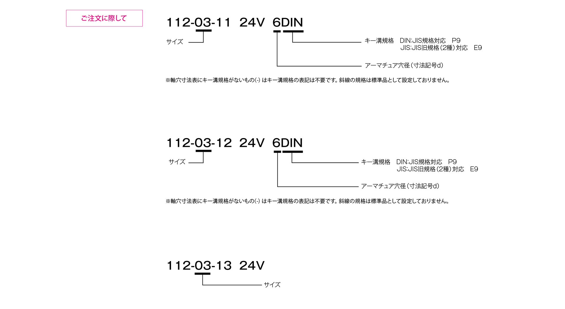
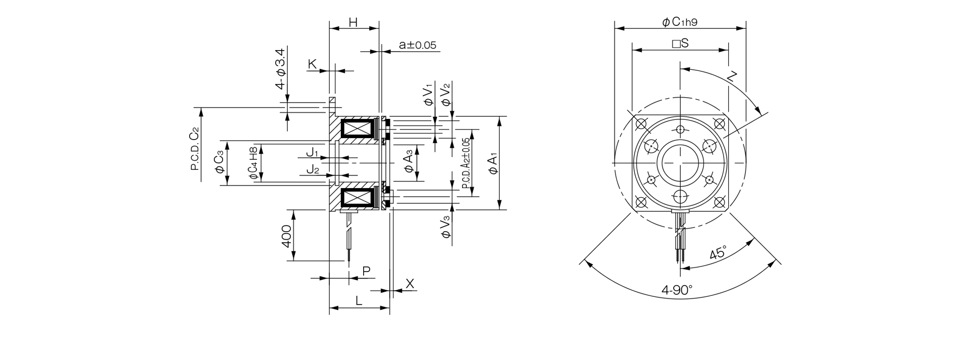
[Dimensions] 112 x □ x 13
| Size | Radial dimensions | Axial dimensions | CAD File No. | ||||||||||||||||||
|---|---|---|---|---|---|---|---|---|---|---|---|---|---|---|---|---|---|---|---|---|---|
| A1 | A2 | A3 | C1 | C2 | C3 | C4 | S | V1 | V2 | V3 | Z | H | K | J1 | J2 | L | P | X | a | ||
| 02 | 28 | 19.5 | 10.5 | 39 | 33.5 | 11.4 | 11 | - | 2-2.1 | 2–5.3 | 2-3.7 | 4–90° | 13.7 | 1.5 | 2.6 | 1.3 | 16.1 | 5 | 0.8 | 0.1 | 112–131 |
| 03 | 32 | 23 | 12.5 | 45 | 38 | 13.6 | 13 | 33 | 3.26 | 3-6 | 3-4.5 | 6–60° | 17 | 2 | 3.3 | 1.3 | 19.3 | 6.7 | 1.2 | 0.15 | 112–132 |
| 04 | 40 | 30 | 18.5 | 54 | 47 | 20 | 19 | 41 | 3-3.1 | 3-6 | 3-5 | 6–60° | 20 | 2 | 3.3 | 1.3 | 22.7 | 7.2 | 1.6 | 0.15 | 112–133 |
| 05 | 50 | 38 | 25.5 | 65 | 58 | 27.2 | 26 | 51 | 3–3.1 | 3-6.5 | 3–6 | 6–60° | 22 | 2 | 3.5 | 1.5 | 25.2 | 8.2 | 1.5 | 0.2 | 112–134 |
- Size 02 features a round flange.
- For information regarding installation methods, please refer to the design specifications.
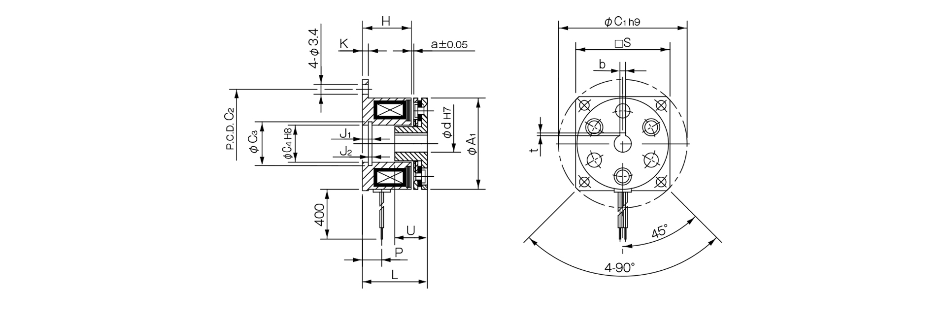
[Dimensions] 112-□-12
Unit [mm]
| Size | Radial dimensions | Axial Dimensions | CAD File No. | ||||||||||||
|---|---|---|---|---|---|---|---|---|---|---|---|---|---|---|---|
| A1 | C1 | C2 | C3 | C4 | S | H | K | J1 | J2 | L | P | U | a | ||
| 02 | 28 | 39 | 33.5 | 11.4 | 11 | - | 13.7 | 1.5 | 2.6 | 1.3 | 18.1 | 5 | 7 | 0.1 | 112–121 |
| 03 | 32 | 45 | 38 | 13.6 | 13 | 33 | 17 | 2 | 3.3 | 1.3 | 21.3 | 6.7 | 10 | 0.15 | 112–122 |
| 04 | 40 | 54 | 47 | 20 | 19 | 41 | 20 | 2 | 3.3 | 1.3 | 25.4 | 7.2 | 12 | 0.15 | 112–123 |
| 05 | 50 | 65 | 58 | 27.2 | 26 | 51 | 22 | 2 | 3.5 | 1.5 | 28.2 | 8.2 | 12 | 0.2 | 112–124 |
Unit [mm]
| Size | Shaft bore dimensions | ||||
|---|---|---|---|---|---|
| d H7 | Compliant with JIS standards | Compliant with Old JIS Standards | |||
| d H7 | b P9 | t | b P9 | t | |
| 02 | 5 | - | - | - | - |
| 03 | 6 | 2–0.006–0.031 | 0.8 + 0.30 | - | - |
| 04 | 8 | 2–0.006–0.031 | 0.8 + 0.30 | - | - |
| 10 | 3–0.006–0.031 | 1.2 + 0.30 | 4 + 0.050 + 0.020 | 1.5 + 0.50 | |
| 05 | 10 | 3–0.006–0.031 | 1.2 + 0.30 | 4 + 0.050 + 0.020 | 1.5 + 0.50 |
| 15 | 5–0.012–0.042 | 2 + 0.50 | 5 + 0.050 + 0.020 | 2 + 0.50 | |
- Size 02 features a round flange.
- The Size 02 armature hub does not have a keyway. Please secure it to the shaft by press-fitting or a similar method.
- For information regarding installation methods and other details, please refer to the design specifications.
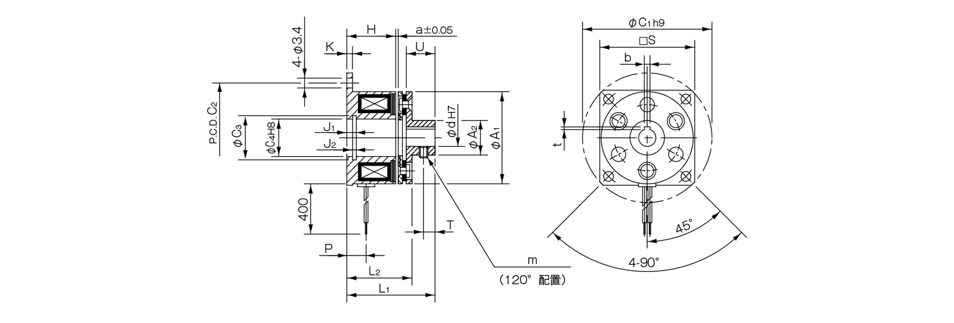
[Dimensions] 112-□-11
Unit [mm]
| Size | Radial dimensions | Axial dimensions | CAD File No. | ||||||||||||||||
|---|---|---|---|---|---|---|---|---|---|---|---|---|---|---|---|---|---|---|---|
| A1 | A2 | C1 | C2 | C3 | C4 | S | m | H | K | J1 | J2 | L1 | L2 | P | U | T | a | ||
| 02 | 28 | 9.5 | 39 | 33.5 | 11.4 | 11 | - | M3 | 13.7 | 1.5 | 2.6 | 1.3 | 23.1 | 18.1 | 5 | 7 | 2.5 | 0.1 | 112-111 |
| 03 | 32 | 12 | 45 | 38 | 13.6 | 13 | 33 | 2-M3 | 17 | 2 | 3.3 | 1.3 | 29.3 | 21.3 | 6.7 | 10 | 4 | 0.15 | 112-112 |
| 04 | 40 | 17 | 54 | 47 | 20 | 19 | 41 | 2-M3 | 20 | 2 | 3.3 | 1.3 | 34.7 | 25.4 | 7.2 | 12 | 5 | 0.15 | 112–113 |
| 05 | 50 | 24 | 65 | 58 | 27.2 | 26 | 51 | 2-M4 | 22 | 2 | 3.5 | 1.5 | 37.2 | 28.2 | 8.2 | 12 | 5 | 0.2 | 112–114 |
Unit [mm]
| Size | Shaft Bore Dimensions | ||||
|---|---|---|---|---|---|
| d H7 | Compliant with JIS standards | Compliant with Old JIS Standards | |||
| d H7 | b P9 | t | b P9 | t | |
| 02 | 5 | - | - | - | - |
| 03 | 6 | 2–0.006–0.031 | 0.8 + 0.30 | - | - |
| 04 | 8 | 2–0.006–0.031 | 0.8 + 0.30 | - | - |
| 10 | 3–0.006–0.031 | 1.2 + 0.30 | 4 + 0.050 + 0.020 | 1.5 + 0.50 | |
| 05 | 10 | 3–0.006–0.031 | 1.2 + 0.30 | 4 + 0.050 + 0.020 | 1.5 + 0.50 |
| 15 | 5–0.012–0.042 | 2 + 0.50 | 5 + 0.050 + 0.020 | 2 + 0.50 | |
- Size 02 features a round flange.
- For information regarding installation methods and other details, please refer to the design specifications.