BSZ Model

This is an electromagnetically operated brake that activates when current is applied to the coil; it is a model designed with an integrated structure based on the 111 (12) type of electromagnetically operated brake. Because it uses a Type 2 armature, it has a short axial dimension and is slim and compact. Since it features an integrated structure, it significantly reduces the time required for tedious installation tasks such as gap adjustment, concentricity checks, and eccentricity adjustment.
[Specifications]
| Model | Size | Dynamic friction torque Td [N·m] | Static friction torque Ts [N·m] | Coil (at 20°C) | Temperature Class | Lead wire | Maximum rotational speed [min⁻¹] | Armature moment of inertia J [kg·m²] | Total work until air gap readjustment ET [J] | Armature pull-in time ta [s] | Torque rise time tp [s] | Torque decay time td [s] | Bearing used | Mass [kg] | ||||
|---|---|---|---|---|---|---|---|---|---|---|---|---|---|---|---|---|---|---|
| Voltage [V] | Power [W] | Current [A] | Resistance [Ω] | UL Style | Size | |||||||||||||
| BSZ-05-12 | 05 | 2.4 | 2.4 | DC24 | 10 | 0.42 | 57 | B | UL3398 | AWG 22 | 1800 | 1.46×10⁻⁵ | 9×10⁶ | 0.020 | 0.030 | 0.010 | 6902ZZ | 0.25 |
| BSZ-06-12 | 06 | 5 | 5.5 | DC24 | 11 | 0.46 | 52 | B | UL3398 | AWG 22 | 1800 | 5.77×10⁻⁵ | 29×10⁶ | 0.017 | 0.033 | 0.010 | 6904ZZ | 0.36 |
| BSZ-08-12 | 08 | 10 | 11 | DC24 | 15 | 0.63 | 38 | B | UL3398 | AWG 18 | 1800 | 1.63×10⁻⁴ | 60×10⁶ | 0.020 | 0.052 | 0.015 | 6905ZZ | 0.67 |
- The dynamic friction torque Td is the value at a relative speed of 100 min⁻¹. Additionally, depending on the initial torque characteristics, a break-in period may be required.
[Dimensions]
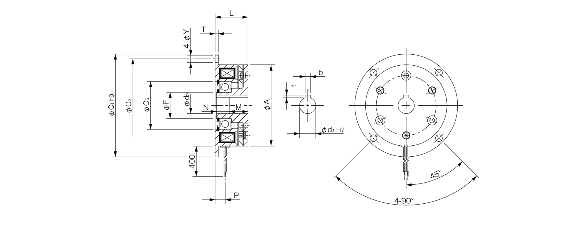
Unit [mm]
| Size | Radial dimensions | Axial dimensions | Bore dimensions | ||||||||||||
|---|---|---|---|---|---|---|---|---|---|---|---|---|---|---|---|
| A | C1 | C2 | C3 | F | L | M | N | P | T | Y | d1H7 | d2 | bH9 | t | |
| 05 | 50 | 65 | 58 | 28 | 15 | 28.3 | 18 | 9.8 | 8.2 | 2 | 3.4 | 10 | 10.2 | 3 + 0.0300 | 1.2 + 0.30 |
| 06 | 63 | 80 | 72 | 37 | 20 | 25.5 | 15 | 10 | 7.3 | 2 | 5 | 12 | 12.2 | 4 + 0.0300 | 1.8 + 0.30 |
| 08 | 80 | 100 | 90 | 42 | 25 | 28.5 | 20 | 8 | 8.3 | 2.6 | 6 | 15 | 15.2 | 5 + 0.0300 | 2.3 + 0.30 |
- For information regarding installation methods, please refer to the design specifications.
