変速機・減速機とは?その種類や構造
2026/05/07
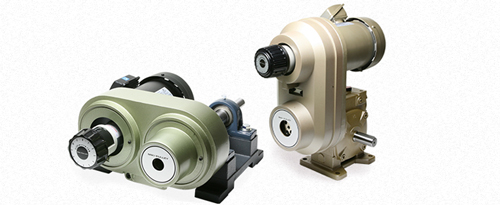
変速機・減速機とは
減速機とは、回転速度を歯車などで減速して出力する装置のことです。減速に対して反比例したトルクを出力することができます。
変速機とは、回転速度の比率を変える装置です。
減速機が一定速なのに対し変速機は速度を変化させることが可能です。
変速機・減速機はなぜ必要なの?
変速機・減速機はモータなどの動力源から得た動力を変速したり減速したりするために利用されます。
それでは変速機・減速機はなぜ必要なのか?それを理解するには少しモータについてを理解する必要があります。
モータとは、電動機、モートル、モーターなどとも呼ばれます。産業機械・装置に使用されるモータにはさまざまな種類がありますが、もっとも一般的に広く利用されているモータは、三相誘導電動機(インダクションモータ)というモータで、このモータは三相交流電源という方式で動作するように作られています。
モータは、電源周波数によって1分間に何回転するかが決まります。
一般に多く利用されるモータとして4極のモータとした場合、日本では東地区50Hz、西地区60Hzの電源周波数のため、東地区では1500min-1(1分間に1500回転)、西地区では1800min-1(1分間に1800回転)の回転速度で回転します。
では、実際に工場などでベルトコンベアーに製品がのって移動している状況を思い浮かべてみましょう。上記のモータ回転速度で運転した場合とんでもない速さでコンベアが運転されることになり、手がつけられる状態ではなくなります。
そこで、一定速で回転しているモータから、 必要な回転速度を得るために、変速機・減速機によって、回転速度を変化・減速させているのです。
つまり、モータから得られる動力を利用する際に必ずといっていいほど、変速機・減速機は必要になるのです。
モータ回転速度は以下の計算式で求めることができます。
・モータの回転速度 N=60×周波数[Hz]/極数/2[min-1]
(*上記の計算式のように、回転速度に影響を与える要素として、投入される電源周波数とモータの極数が挙げられます。)
まとめ 変速機・減速機の役割①
・モータなどの回転速度を、変速機や減速機によって変化・減速させる。
変速・減速の原理
変速機・減速機は必要な回転速度を得る装置であることを述べてきましたが、もう一つ大事な役割があります。
それが、減速比に比例した回転力(トルク)を得ることです。たとえば、回転速度を1/2とするとその回転力(トルク)は2倍となります。
これは、変速・減速のしくみがてこの原理を利用しているためです。
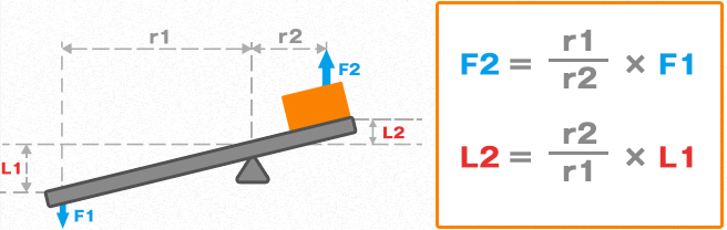
上図はてこの原理を表していて、上図の計算式はF1の力でF2という大きな力が得られることを示しています。また、L1の移動距離に対してL2の移動距離が短いことが分かります。
この原理をわかりやすく回転体に置き換えて図示すると以下のようになります。
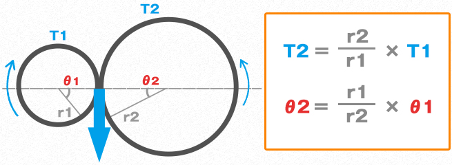
したがって、回転速度を下げることで回転力を大きくすることができるのです。
まとめ 変速機・減速機の役割②
・減速比に比例した回転力(トルク)を得ることができる。
変速機と減速機の違い
どちらもモータの回転速度を減速させ、必要な力を得るためのものですが、減速機が一定速なのに対し変速機は速度を変化させることが可能であるという大きな違いがあります。
減速機で大幅な減速をしておき、変速機でその速度を調節するといった利用方法が最適な動力の取り出し方の一つであると言えます。
まとめ 変速機と減速機の役割と違い
・減速機は一定速での回転だが、変速機は回転速度を変化させることができる
減速機の種類と構造
歯数の異なる平歯車を組み合わせることで、減速機構は比較的容易に実現できますが、減速機として装置化されているものを利用する方法が一般的です。
代表的な減速機としては、以下の方式が挙げられます。ただし、必要な減速比率を確保するために、以下で述べているギアを組み合わせて減速機として実現している場合が一般的です。
| 種類 | 特長 |
|---|---|
| 平行軸歯車減速機 | 平歯車(スパーギア)を組み合わせた減速機で、減速比率によって1段から4段用意されています。 動力の伝達は、転がりによるため、1段あたり98%程度の伝達効率が確保できます。 減速比率は1/5~1/2500程度と幅広い減速比率をカバーできます。 減速比率によって組み合わせる歯車の段数に違いがあるため、適応モータ出力によって減速機の寸法が変わります。 |
| ヘリカル減速機 | 平行軸歯車減速機と同様ですが、歯車にヘリカルギア(はすば歯車)を使用。 ヘリカルギアは、歯すじをねじらせた歯車で、それにより歯のかみ合い率が向上し、なめらかで静粛性の高い動力伝達が得られます。 ただし、歯すじがななめになっているため、動力伝達の大きさに比例してスラスト力が発生するという弱点があります。 このスラスト力を打ち消すための真逆のヘリカルギアを配置したダブルヘリカルギアで弱点を克服可能です。 |
| べベルギア減速機 | かさ歯車を組み合わせた減速機で、一般的な軸角は90°です。 小歯車と大歯車を組み合わせることで減速すしますが、出力を90°振るために用いられることが多く、そのため、べベル減速機の中でも減速比率が1:1の場合マイタギアとも呼ばれます。 ヘリカルギアと同様に、かさ歯車の歯すじをねじらせかみ合い率を向上させたものをスパイラルべベルギア(まがり歯かさ歯車)と呼ばれます。 |
| ハイポイド減速機 | 上述のスパイラルべベルギアに対して、ピニオンギアの軸心をギア軸中心に対してある量だけオフセットして配置したギアです。 後述するウォーム減速機のようにスパイラルべベルギアの動力伝達に滑りを加えることで、さらに滑らかな動力伝達が可能です。 ウォーム減速機同様に歯数比が大きいため、大きな減速比率を得ることができます。 ただし、かみ合いが複雑なため、かみ合い位置を精密に調整する必要あります。 |
| ウォーム減速機 | ねじ歯車(ウォームギア)とはす歯歯車(ウォームホイール)を組み合わせた減速機で、この組み合わせだけで1/10~1/60程度の大きな減速比率が得られます。 ねじ歯車(ウォームギア)の進み角が小さく(減速比率が高く)なるとセルフロックと呼ばれ、はす歯歯車(ウォームホイール)側(出力側)から回すことが困難になることを利用し、昇降装置の落下防止などに利用可能です。 また、入力軸のスラストガタを少なくすることで、バックラッシを抑えることが可能であり、さまざまなメリットのある減速機です。 ただし、平歯車と比べ動力伝達を歯面のすべりによっておこなうため、熱を発生しやすく、伝達効率は50%程度とあまり良好ではありません。 |
変速機の種類
装置を運転する上で、形や大きさ、重さの異なる物体を扱う場面では、ある一定の速度のみでその装置を扱うことで著しく効率を損なうことがあります。
そこで、一つの装置がさまざまな速度で運転できる方が運転効率は良くなります。
例えば、必要な速度が2種類であると決まっている場合、2種類の速度が出力できればよいわけです。
方法としては、有段の変速機構を利用しクラッチなどで切り替えて速度を取り出したり、2種類の出力に対して機械を一旦止めて切り替えたりする方法も考えられます。
しかしそれよりも、原動機を止めずに無段階で出力速度を調節できた方が圧倒的に便利で効率が良いです。
これが、変速機の分類でいうところの有段変速機に対する無段変速機です。
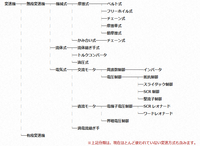
三木プーリが現在も扱っている無段変速機としては、以下の分類になります。
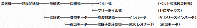
三相誘導電動機(インダクションモータ)の周波数を変化させることで変速させたり、そもそも三相誘導電動機ではない直流モータなどの電気式については別途まとめることとし、ここでは社名の一部となっている可変ピッチプーリを用いたベルト式無段変速機の種類とその原理についてをまとめていきます。
ベルト式無段変速機の種類と構造
駆動機(モータ)から被動機(機械)への動力の伝達を区分けした場合、モータの出力をダイレクトに伝えるカップリングや減速機のような歯車、チェーン・スプロケットやベルト・プーリによる巻き掛けなどの方法が一般的です。
通常のベルト・プーリの動力伝達ではベルトのピッチ径が固定されており、予め必要な回転速度と回転力が得られるように選定し、一定速を得ます。
ベルト式無段変速機とは、ベルト・プーリを使った無段変速機で、ベルトの掛かるプーリのピッチ径を変化させることで、一定回転の入力を変化させるものです。その変速方法には、大きく分けて3種類の方式があります。

| 種類 | 特長 |
|---|---|
| 中間可変ピッチ型 | 駆動機と被動機の中間に中間可変ピッチ型変速機を配置し、中間可変ピッチ型プーリを駆動機側、被動機側へ移動させることで変速します。 中間可変ピッチ型プーリはV溝の2つあるプーリとなっており、真ん中のプーリ面が軸方向に自由に移動します。 ベルトは2つあるV溝の一方を駆動機側、一方を被動機側へ接続することで、駆動機と被動機の位置は固定のまま、中間車型変速機を移動させることで、駆動・被動のベルトピッチ径を変化させ変速します。 入手性のよい標準Vベルトを採用した設計となっているのでメンテナンス性もよく、中間配置のプーリのみで変速機能を実現できるためコストを抑えた変速機構を実現できます。 ただし、駆動機と被動機の間に設置し、双方に移動させる必要があるため、その分軸間距離は大きくなり場合によっては装置の肥大化を招くことがあります。 >L型・U型・T型 |
| シングル可変ピッチ型 | 被動機側には固定ピッチプーリを配置し、駆動機側にシングル可変ピッチ型プーリを配置し、駆動機を移動させ軸間距離を変えることで、変速します。 シングル可変ピッチ型プーリは内蔵されたスプリングによって、プーリは常に閉じようとする力が加わっています。 そこで、軸間距離を広げることでベルトがプーリのスプリングを押し広げピッチ径を変化させ、変速します。 入手性のよい標準Vベルトを採用したモデルと伝達能力の高い変速ベルトを採用したモデルがあり、いずれも変速比が比較的小さい場合に適しています。また、駆動機(モータ)を移動させるための装置が別途必要になります。 >P型・PL型(標準Vベルト) >PK型・PF型(幅広変速ベルト) >R型・RK型・RH型(モータ移動台) |
| ダブル可変ピッチ型 | 被動機側には、上述のシングル可変ピッチプーリを配置し、駆動機側には強制的にプーリの開閉を可能にしたプーリを配置することで、変速します。 駆動機側のプーリに回転ハンドルを設け、送りねじによってプーリ面の開閉をおこないます。被動機側のプーリには内蔵されたスプリングによって常に閉じようとする力が加わっています。 そこで、駆動機側のプーリのハンドルを手動で回転させることで、駆動機側・被動機側双方のプーリピッチ径を変化させることで、軸間距離を変化させることなく変速します。 入手性のよい標準Vベルトを採用したモデルと伝達能力の高い変速ベルトを採用したモデルがあり、比較的大きな変速比率が得られます。また、軸間距離を移動させる必要がないため、モータ・減速機などと一体化させたユニットとして提供することが可能です。 >PSS型(標準Vベルト)、AP型+P型 >ANS型・PDS型・AHS型(幅広変速ベルト)、AK型+PE型 >PDC型・PDG型・PDV型・ANW型・ANG型・ACW型・ANB型・ANV型、AHM型(ベルト式無段変速機ユニット) |
コンテンツ一覧
熟練の技術者がお客様の設備に合わせた変速機・減速機を選定いたします!
お客様の設備になにかお困りごとはありませんか?
三木プーリではお客様の設備に合わせた変速機や減速機を、多数のバリエーションの中から選定・カスタマイズいたします!
以下のフォームよりお気軽にご相談くださいませ。