CF-X [O2-C] Clamp-Type

Power is transmitted via a backlash-free design and nylon resin elements. This design is rigid in the torsional direction and highly flexible in the lateral and axial directions, enabling precise power transmission while absorbing vibrations and shocks.The clamp type utilizes a hub clamp mechanism to take full advantage of the zero-backlash characteristics.
[Specifications]
| Model | Torque | Tolerance | Maximum rotational speed [min⁻¹] | Static torsional spring constant [N·m/rad] | Moment of inertia [kg·m²] | Mass [kg] | Price for pre-drilled holes [JPY] | |||
|---|---|---|---|---|---|---|---|---|---|---|
| Rated torque [N·m] | Maximum [N·m] | Eccentricity [mm] | Angular Deviation [°] | Axial [mm] | ||||||
| CF-X-001-C | 15 | 30 | 0.1 | 1 | ±0.5 | 10,000 | 3.0×10³ | 1.22×10⁻⁴ | 0.5 | |
| CF-X-002-C | 30 | 60 | 0.1 | 1 | ±0.5 | 10,000 | 6.0×10³ | 5.74×10⁻⁴ | 0.9 | |
| CF-X-004-C | 60 | 120 | 0.1 | 1 | ±0.5 | 8000 | 2.3×10⁴ | 1.19×10⁻³ | 1.4 | |
| CF-X-008-C | 120 | 250 | 0.1 | 1 | ±0.5 | 7000 | 5.8×10⁴ | 3.49×10⁻³ | 2.9 | |
| CF-X-016-C | 240 | 500 | 0.1 | 1 | ±0.5 | 6000 | 1.1×10⁵ | 9.20×10⁻³ | 5.0 | |
| CF-X-025-C | 370 | 800 | 0.1 | 1 | ±0.5 | 5000 | 1.7×10⁵ | 1.83×10⁻² | 7.9 | |
- The maximum rotational speed does not take dynamic balance into account.
- The values for the static torsional spring constant are given at 20°C.
- The values for moment of inertia and mass apply to cylindrical hubs and flanged hubs with a through-bore.
[Dimensions]
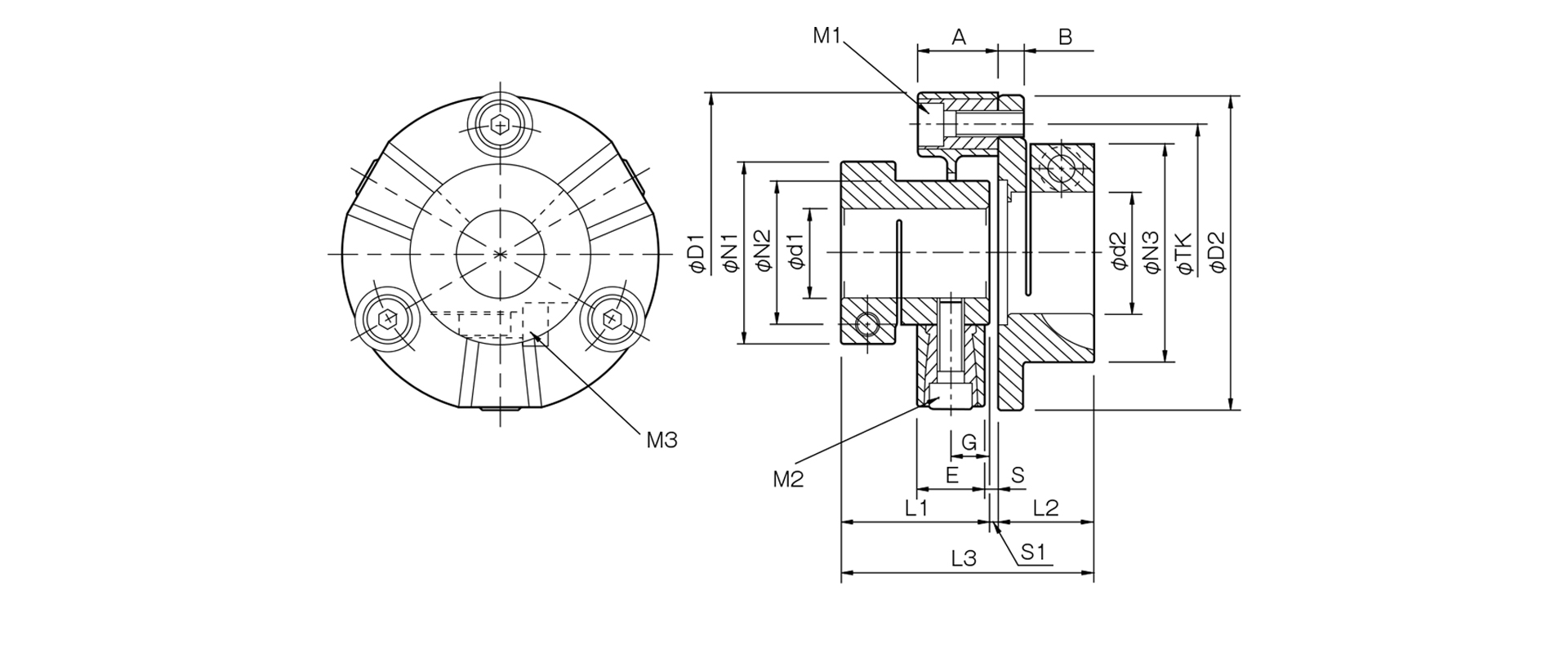
Unit [mm]
| Model | d1 | d2 | D1 | D2 | N1 | N2 | N3 | L1 | L2 | L3 | A | B | E | G | S | S1 | M1 | M2 | M3 | TK | ||
|---|---|---|---|---|---|---|---|---|---|---|---|---|---|---|---|---|---|---|---|---|---|---|
| Minimum | Max | Min | Max | |||||||||||||||||||
| CF-X-001-O2-C | 10 | 16 | 10 | 19 | 57 | 56 | 33 | 30 | 38 | 37 | 24 | 62 | 24 | 7 | 18 | 11 | 3 | 1 | 2-M6 | 2-M6 | 1-M5 | 44 |
| CF-X-002-O2-C | 12 | 25 | 12 | 25 | 88 | 85 | 46 | 40 | 46 | 43 | 28 | 75 | 24 | 8 | 20 | 10 | 4 | 4 | 2-M8 | 2-M8 | 1-M6 | 68 |
| CF-X-004-O2-C | 14 | 28 | 14 | 38 | 100 | 99 | 57 | 45 | 68 | 46.5 | 30 | 79 | 25 | 8 | 21 | 12 | 4 | 2.5 | 3-M8 | 3-M8 | 1-M8 | 80 |
- The designations for M1, M2, and M3 bolts consist of the quantity followed by the thread size; for M3 clamping bolts, the quantity refers to the number of bolts on one side of the hub.
- The recommended machining tolerance for the mating shaft is h7.
[Standard Hole Diameter]
| Model | Standard Hole Diameter [mm] |
|||||||||||||||||
|---|---|---|---|---|---|---|---|---|---|---|---|---|---|---|---|---|---|---|
| 10 | 11 | 12 | 14 | 15 | 16 | 18 | 19 | 20 | 22 | 24 | 25 | 28 | 32 | 30 | 35 | 38 | ||
| CF-X-001-O2-C | d1 | ● | ● | ● | ● | ● | ● | |||||||||||
| d2 | ● | ● | ● | ● | ● | ● | ● | ● | ||||||||||
| CF-X-002-O2-C | d1 | ● | ● | ● | ● | ● | ● | ● | ● | ● | ● | |||||||
| d2 | ● | ● | ● | ● | ● | ● | ● | ● | ● | ● | ||||||||
| CF-X-004-O2-C | d1 | ● | ● | ● | ● | ● | ● | ● | ● | ● | ● | |||||||
| d2 | ● | ● | ● | ● | ● | ● | ● | ● | ● | ● | ● | ● | ● | ● | ||||