CF-X [O0] Type

Power is transmitted via a backlash-free design featuring nylon resin elements. This design is rigid in the torsional direction and highly flexible in the lateral and axial directions, enabling precise power transmission while absorbing vibrations and shocks. The O0 type is available with nylon resin elements only.
[Specifications]
| Model | Torque | Tolerance | Maximum Rotational Speed [min⁻¹] |
Static Torsional Spring Constant [N·m/rad] |
|||||
|---|---|---|---|---|---|---|---|---|---|
| Rated [N·m] |
Maximum [N·m] |
Eccentricity [mm] |
Angular offset [°] |
Axial length [mm] |
Moment of inertia [kg·m²] |
Mass [kg] |
|||
| CF-X-001-O0 | 15 | 30 | 0.1 | 1 | ±0.5 | 10,000 | 3.0×10³ | 2.03×10⁻⁵ | 0.04 |
| CF-X-002-O0 | 30 | 60 | 0.1 | 1 | ±0.5 | 10,000 | 6.0×10³ | 9.75×10⁻⁵ | 0.1 |
| CF-X-004-O0 | 60 | 120 | 0.1 | 1 | ±0.5 | 8000 | 2.3×10⁴ | 2.30×10⁻⁴ | 0.2 |
| CF-X-008-O0 | 120 | 250 | 0.1 | 1 | ±0.5 | 7,000 | 5.8×10⁴ | 6.63×10⁻⁴ | 0.3 |
| CF-X-016-O0 | 240 | 500 | 0.1 | 1 | ±0.5 | 6000 | 1.1×10⁵ | 1.56×10⁻³ | 0.5 |
| CF-X-025-O0 | 370 | 800 | 0.1 | 1 | ±0.5 | 5000 | 1.7×10⁵ | 2.77×10⁻³ | 0.6 |
[Dimensions]
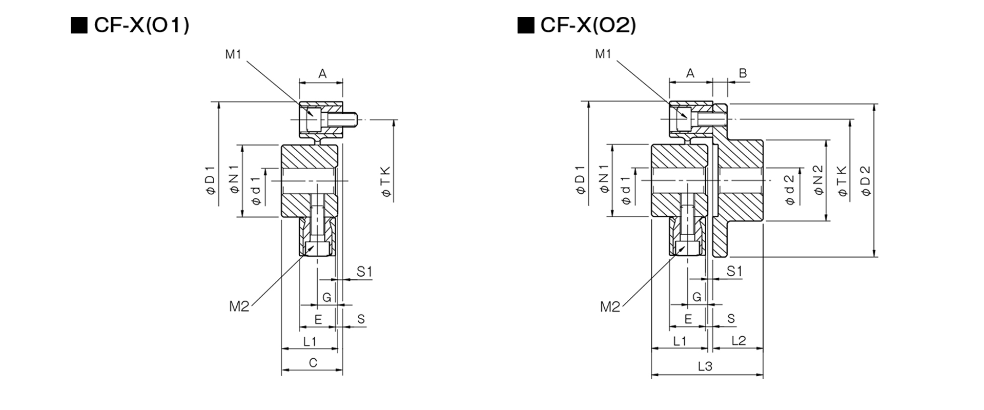
Unit [mm]
| Model | d1 | d2 | D1 | D2 | N1 | N2 | L1 | L2 | L3 | A | B | C | E | G | S | S1 | M1 | M2 | TK | CAD File No. | ||||
|---|---|---|---|---|---|---|---|---|---|---|---|---|---|---|---|---|---|---|---|---|---|---|---|---|
| Pilot hole | Min. | Max | Pilot hole | Min | Max | |||||||||||||||||||
| CF-X-001 | 8 | 9 | 19 | 8 | 9 | 22 | 57 | 56 | 30 | 36 | 32 | 24 | 57 | 24 | 7 | 33 | 18 | 11 | 3 | 1 | 2-M6 | 2-M6 | 44 | CF-X1 |
| CF-X-002 | 10 | 11 | 26 | 9 | 10 | 30 | 88 | 85 | 40 | 45 | 30 | 28 | 62 | 24 | 8 | 34 | 20 | 10 | 4 | 4 | 2-M8 | 2-M8 | 68 | CF-X2 |
| CF-X-004 | 12 | 14 | 30 | 11 | 12 | 36 | 100 | 100 | 45 | 55 | 34 | 30 | 66.5 | 25 | 8 | 36.5 | 21 | 12 | 4 | 2.5 | 3-M8 | 3-M8 | 80 | CF-X3 |
| CF-X-008 | 12 | 14 | 38 | 15 | 16 | 46 | 125 | 120 | 60 | 70 | 40 | 42 | 85 | 30 | 10 | 43 | 26 | 14 | 4 | 3 | 3-M10 | 3-M10 | 100 | CF-X4 |
| CF-X-016 | 15 | 16 | 48 | 19 | 20 | 56 | 155 | 150 | 70 | 85 | 52 | 50 | 105 | 35 | 12 | 55 | 28 | 18 | 7 | 3 | 3-M12 | 3-M12 | 125 | CF-X5 |
| CF-X-025 | 15 | 16 | 55 | 19 | 20 | 65 | 175 | 170 | 85 | 100 | 58 | 56 | 117 | 40 | 14 | 61 | 34 | 20 | 6 | 3 | 3-M14 | 3-M14 | 140 | CF-X6 |
- The designation for M1 and M2 bolts is based on the quantity and thread size.
- The TK dimension refers to the bolt mounting pitch diameter of the flange hub or mating mounting surface.