SFR Model
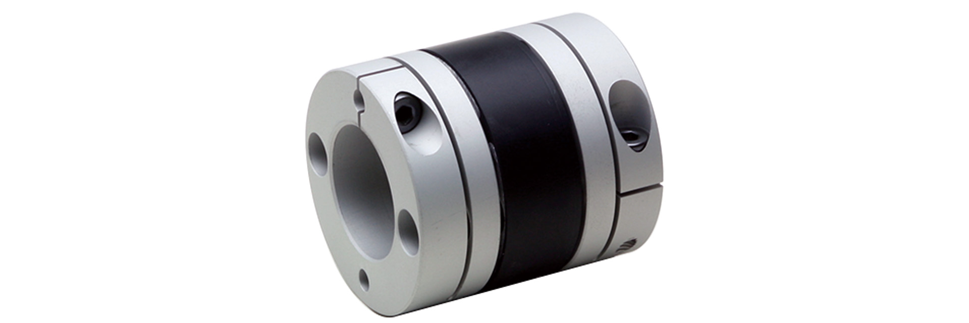
This is a high-damping rubber coupling designed for servo and stepper motors. Our newly developed rubber element delivers high damping and low reaction force. It absorbs vibrations more quickly than flexible couplings that use metal in their elastic components. This helps suppress resonance phenomena that are a concern with stepper motors and similar applications.
[Specifications]
| Model | Shape: TYPE | Torque | Tolerance | Maximum Rotational Speed [min⁻¹] |
Torsional Spring Constant [N·m/rad] |
Moment of Inertia [kg·m²] |
Mass [kg] | Price [JPY] | ||
|---|---|---|---|---|---|---|---|---|---|---|
| Rated load [N·m] |
Eccentricity [mm] |
Angular Deviation [°] |
Axial [mm] |
|||||||
| SFR-005SA1 | C | 0.6 | 0.15 | 1.5 | ±0.2 | 10,000 | 30 | 0.32×10⁻⁶ | 0.009 | 7,230 |
| SFR-010SA1 | 1 | 47 | 0.73×10⁻⁶ | 0.014 | 6,120 | |||||
| SFR-020SA1 | 2 | 178 | 3.11×10⁻⁶ | 0.032 | 7,080 | |||||
| SFR-025SA1 | 4 | 0.2 | ±0.3 | 254 | 4.88×10⁻⁶ | 0.038 | 7,600 | |||
| SFR-030SA1 | A | 5 | 396 | 6.62×10⁻⁶ | 0.048 | 8,050 | ||||
| B | 5 | 396 | 8.65×10⁻⁶ | 0.054 | 8,050 | |||||
| C | 5 | 396 | 10.76×10⁻⁶ | 0.063 | 8,050 | |||||
| SFR-035SA1 | C | 10 | 607 | 26.98×10⁻⁶ | 0.105 | 9,330 | ||||
| SFR-040SA1 | A | 12 | 1128 | 25.37×10⁻⁶ | 0.103 | 11,250 | ||||
| B | 12 | 1128 | 31.96×10⁻⁶ | 0.114 | 11,250 | |||||
| C | 12 | 1128 | 38.64×10⁻⁶ | 0.128 | 11,250 | |||||
| SFR-050SA1 | A | 25 | 2775 | 85.36×10⁻⁶ | 0.216 | 13,660 | ||||
| B | 25 | 2775 | 105.75×10⁻⁶ | 0.234 | 13,660 | |||||
| C | 25 | 2775 | 128.36×10⁻⁶ | 0.263 | 13,660 | |||||
- The shape type (A, B, or C) is automatically determined based on the combination of hole diameters you select, so you cannot specify it.
- The allowable torque may be limited by the holding force of the shaft fastening section, so please check the "standard bore diameter."
- The maximum rotational speed does not take dynamic balance into account.
- The torsional spring constant values are the analytical results for the element section at 20°C.
- The moment of inertia and mass are based on the maximum bore diameter.
[Dimensions]
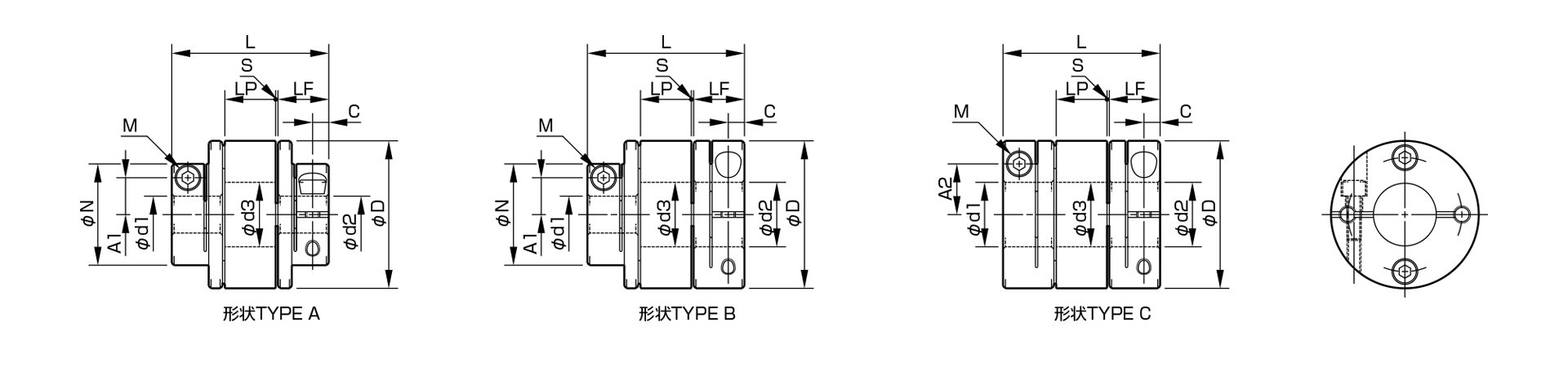
| Model | Shape TYPE | d1 [mm] | d2 [mm] | D[mm] | N[mm] | L[mm] | LF[mm] | LP[mm] | S[mm] | A1[mm] | A2[mm] | C[mm] | d3 [mm] |
M Quantity - Nominal |
Tightening torque [N·m] |
||
|---|---|---|---|---|---|---|---|---|---|---|---|---|---|---|---|---|---|
| Minimum | Max | Min | Max | ||||||||||||||
| SFR-005SA1 | C | 3 | 5 | 3 | 6 | 16 | - | 22.7 | 7.85 | 6.4 | 0.3 | - | 4.8 | 2.5 | 5.5 | 1-M2 | 0.4–0.5 |
| SFR-010SA1 | 7 | 8 | 19 | 25.4 | 9.15 | 6.6 | 0.25 | 5.8(6) | 3.15 | 7.5 | 1–M2.5 (M2) | 1.0–1.1 (0.4–0.5) | |||||
| SFR-020SA1 | 4 | 10 | 4 | 11 | 26 | 31.8 | 10.75 | 8.9 | 0.7 | 9.5 | 3.3 | 10.5 | 1–M2.5 | 1.0–1.1 | |||
| SFR-025SA1 | 5 | 13 | 5 | 14 | 29 | 32.3 | 9.4 | 11 | 13.5 | ||||||||
| SFR-030SA1 | A | 10 | 10 | 34 | 21.6 | 37.8 | 12.4 | 11 | 1 | 8 | - | 3.75 | 15.5 | 1-M3 | 1.5–1.9 | ||
| B | 10 | Over 10 | 16 | 34 | 21.6 | 37.8 | 12.4 | 11 | 1 | 8 | 12.5 | 3.75 | 15.5 | 1-M3 | 1.5–1.9 | ||
| C | Over 10 | 15 | Over 10 | 16 | 34 | - | 37.8 | 12.4 | 11 | 1 | - | 12.5 | 3.75 | 15.5 | 1-M3 | 1.5–1.9 | |
| SFR-035SA1 | C | 6 | 18 | 6 | 19 | 39 | - | 48 | 15.5 | 15 | 1 | - | 14 | 4.5 | 18.5 | 1-M4 | 3.4–4.1 |
| SFR-040SA1 | A | 8 | 15 | 8 | 15 | 44 | 29.6 | 11 | - | 23.5 | |||||||
| B | 8 | 15 | Over 15 | 24 | 44 | 29.6 | 11 | 17 | 23.5 | ||||||||
| C | Exceeding 15 | 22 | Over 15 | 24 | 44 | - | - | 17 | 23.5 | ||||||||
| SFR-050SA1 | A | 8 | 19 | 8 | 19 | 56 | 38 | 59.8 | 20.5 | 17.4 | 0.7 | 14.5 | - | 6 | 29.5 | 1-M5 | 7.0–8.5 |
| B | 8 | 19 | Over 19 | 30 | 56 | 38 | 59.8 | 20.5 | 17.4 | 0.7 | 14.5 | 22 | 6 | 29.5 | 1-M5 | 7.0–8.5 | |
| C | Over 19 | 28 | Over 19 | 30 | 56 | - | 59.8 | 20.5 | 17.4 | 0.7 | - | 22 | 6 | 29.5 | 1-M5 | 7.0–8.5 | |
- The shape type (A, B, or C) is automatically determined based on the combination of hole diameters you select, so you cannot specify it.
- The d3 dimension is the inner diameter of the element. If the d2 dimension exceeds this value, the shaft can only be inserted into the hub on the d2 side up to the LF dimension.
- The designation for Clamp Bolt M consists of the quantity followed by the thread size; the quantity refers to the number of bolts on one side of the hub.
[Standard Hole Diameter]
| Standard (optional) hole diameters d1 and d2 [mm] and the maximum torque [N·m] | |||||||||||||||||||||||||||
|---|---|---|---|---|---|---|---|---|---|---|---|---|---|---|---|---|---|---|---|---|---|---|---|---|---|---|---|
| Nominal Bore Diameter | 3 | 4 | 5 | 6 | 6.35 | 7 | 8 | 9 | 9.525 | 10 | 11 | 12 | 13 | 14 | 15 | 16 | 17 | 18 | 19 | 20 | 22 | 24 | 25 | 28 | 30 | ||
| Shaft tolerance | h7 (h6·g6) | B | ● | ● | ● | ● | ● | ● | ● | ● | ● | ● | ● | ● | ● | ● | ● | ● | ● | ● | ● | ● | ● | ● | ● | ● | ● |
| j6 (optional) | J | 〇 | 〇 | ✓ | ✓ | ||||||||||||||||||||||
| k6 (optional) | K | 〇 | 〇 | 〇 | ✓ | 〇 | 〇 | 〇 | |||||||||||||||||||
| Compatible Hole Diameters by Model | SFR-005SA1 | d1 | ● | ● | ● | ||||||||||||||||||||||
| SFR-005SA1 | d2 | ● | ● | ● | ● | ||||||||||||||||||||||
| SFR-010SA1 | d1 | ● | ● | ● | ● | ● | ● | ||||||||||||||||||||
| SFR-010SA1 | d2 | ● | ● | ● | ● | ● | ● | ● | |||||||||||||||||||
| SFR-020SA1 | d1 | ● | ● | ● | ● | ● | ● | ● | ● | ● | |||||||||||||||||
| SFR-020SA1 | d2 | ● | ● | ● | ● | ● | ● | ● | ● | ● | ● | ||||||||||||||||
| SFR-025SA1 | d1 | 2.1 | ● | ● | ● | ● | ● | ● | ● | ● | ● | ● | |||||||||||||||
| SFR-025SA1 | d2 | 2.1 | ● | ● | ● | ● | ● | ● | ● | ● | ● | ● | ● | ||||||||||||||
| SFR-030SA1 | d1 | 2.8 | 3.4 | ● | ● | ● | ● | ● | ● | ● | ● | ● | ● | ● | |||||||||||||
| SFR-030SA1 | d2 | 2.8 | 3.4 | ● | ● | ● | ● | ● | ● | ● | ● | ● | ● | ● | ● | ||||||||||||
| SFR-035SA1 | d1 | 5 | 5 | 6.6 | ● | ● | ● | ● | ● | ● | ● | ● | ● | ● | ● | ● | |||||||||||
| SFR-035SA1 | d2 | 5 | 5 | 6.6 | ● | ● | ● | ● | ● | ● | ● | ● | ● | ● | ● | ● | ● | ||||||||||
| SFR-040SA1 | d1 | 9 | ● | ● | ● | ● | ● | ● | ● | ● | ● | ● | ● | ● | ● | ● | |||||||||||
| SFR-040SA1 | d2 | 9 | ● | ● | ● | ● | ● | ● | ● | ● | ● | ● | ● | ● | ● | ● | ● | ||||||||||
| SFR-050SA1 | d1 | 18 | 20 | 22 | 22 | ● | ● | ● | ● | ● | ● | ● | ● | ● | ● | ● | ● | ● | ● | ||||||||
| SFR-050SA1 | d2 | 18 | 20 | 22 | 22 | ● | ● | ● | ● | ● | ● | ● | ● | ● | ● | ● | ● | ● | ● | ● | |||||||
- The standard bore diameter for shaft tolerance h7 (h6, g6) is nominal B.
- For shaft tolerances j6 and k6: Nominal sizes J and K are available as options; only the hole diameters marked with a circle are supported.
- The hole diameters indicated by the ● symbol and numerical values in the corresponding columns are standard sizes. For hole diameters not listed in the table above, we may be able to accommodate your request; please contact us for details.
- Because the hole diameter in the column containing the numerical values is small, the allowable torque is limited by the holding force at the shaft fastening point. The numerical values indicate the allowable torque [N·m].