Balance Quality of Rotating Equipment
2026/05/07
According to JIS B 0153-1985, "balance" is defined as "a quantity indicating the degree of balance of a rigid rotor, equal to the product of the specific unbalance and a specified angular velocity."
Procedure for Determining Tolerance Imbalance
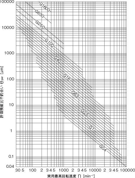
To determine the allowable imbalance, the following information (numerical values) regarding the rotor is required: The maximum rotational speed nmax at which the rotor is used The mass m of the rotor The position of the rotor bearings The position of the balancing surface For more detailed calculations, the position of the rotor’s center of mass is required. The balance grade is determined based on the type of rotor. The lower the balance grade value, the higher the balancing accuracy. However, as noted in the JIS commentary, special attention is required for G1 and G0.4. The permissible residual unbalance ratio eper is determined based on the maximum rotational speed at which the rotor will actually be used. This can be calculated using the following formula or the diagram on the right. Balance grade = e × ω ω = 2πn/60 = n/9.55 n [min⁻¹] ω [rad/s] Balance grade = e × n 9.55 Determine the allowable residual unbalance from the allowable residual unbalance ratio and the rotor mass. Allowable residual unbalance Uper = eperm [g·mm] Distribute the allowable residual unbalance to the actual unbalanced surfaces (Note: The calculation method for distribution varies depending on the relationship between bearing position, unbalanced surface position, mass, and center of mass; refer to the JIS standard for details).
Recommended balance grades for various rotating machines (JIS B 0905-1992)
| Balance Grade |
Upper Limit for Balance, mm/s (eper × ω) |
Example of Rotor Types |
|---|---|---|
| G4000 | 4000 | ● Crank shaft systems*2 of marine low-speed diesel engines*1 with an odd number of rigidly supported cylinders |
| G1600 | 1600 | ● Crankshaft systems for rigidly supported large two-stroke engines*2 |
| G630 | 630 | ● Rigidly supported crankshaft systems for large 4-cycle engines*2 ● Elastically supported crankshaft systems for marine diesel engines*1*2 |
| G250 | 250 | ● Rigidly supported crankshaft systems for high-speed 4-cylinder diesel engines*1*2 |
| G100 | 100 | ● Crankshaft systems for high-speed diesel engines with 6 or more cylinders*1 Complete engines (gasoline or diesel) for automobiles, trucks, and railway vehicles |
| G40 | 40 | ● Automotive wheels, rims, wheel sets, and drive shafts ● Crank shaft systems for high-speed 4-cycle engines*1 with 6 or more cylinders (gasoline or diesel) ● Crank shaft systems*2 for automotive, truck, and railway vehicle engines*2 |
| G16 | 16 | ● Drive shafts with special requirements (propeller shafts, cardan shafts) ● Parts for crushers ● Parts for agricultural machinery ● Parts for engines (gasoline, diesel) in automobiles, trucks, and railway vehicles ● Crankshaft systems with special requirements for engines with 6 or more cylinders*2 |
| G6.3 | 6.3 | ● Process plant equipment ● Marine main engine turbine gears (for merchant ships) ● Centrifuge drums ● Paper and printing rolls ● Fans ● Assembled aircraft gas turbine rotors ● Flywheels ● Pump impellers ● Machine tool and general machinery components ● Medium- and large-sized armature (for electric motors with a minimum shaft center height of 80 mm) without special requirements ● Small armature (primarily mass-produced) used in applications insensitive to vibration or equipped with vibration isolation ● Engine components with special requirements |
| G2.5 | 2.5 | ● Gas turbines, steam turbines, and marine main engine turbines (for merchant ships) ● Rigid turbo-generator rotors ● Computer storage drums and disks ● Turbo compressors ● Machine tool spindles ● Medium- and large-sized armatures with special requirements ● Small armatures (excluding those meeting the conditions of G6.3 and G1) ● Turbine-driven pumps |
| G1 | 1 | ● Rotating parts of tape recorders and audio equipment ● Grinding wheel spindles ● Small electronic machines with special requirements |
| G0.4 | 0.4 | ● Grinding spindles, grinding wheels, and armatures in precision grinding machines ● Gyroscopes |
* Note 1: Diesel engines with a piston speed of 9 m/s or less are classified as low-speed engines, while those exceeding this speed are classified as high-speed engines.
※ *2: The crankshaft system refers to the entire assembly comprising the rotating parts of the crankshaft, flywheel, clutch, pulley, damper, and connecting rods.
※ For a complete engine, the mass of its rotor refers to the total mass of all components belonging to the crankshaft system.
Other Technical Documents
↓You can download a compilation of the technical documents below as a PDF.
Specifications
Hole Machining, Tolerances, and Fits
Calculations, Conversions, Formulas, and Units
Machine Elements
- Hexagon Socket Head Cap Screws (Cap Bolts) Standards List | Excerpt from JIS B 1176
- Shapes and Dimensions of Hex Socket Set Screws (Excerpt from JIS B 1177-1997)
- Shapes and Dimensions of Hex Bolts (Part Grade A) (Excerpt from JIS B 1180-1985)
- How to Use Hex Socket Set Screws
- Mechanical Properties of Steel Bolts and Screws (Excerpt from JIS B 1051-2000)
- Shapes and Dimensions of Hexagonal Wrenches (Hex Wrenches/L-Wrenches/Hex Wrenches) (Excerpt from JIS B 4648:2008)
- Dimensions and Tolerances of Parallel Keys and Keyways: List of Standards (Excerpt from JIS B 1301-1996/JIS B 1301-1959 [Old JIS])
- Snap Rings (C-Clips/C-Rings) Standards and Dimensions List (Excerpt from JIS B 2804-2010)
- Shim Dimensions
- Ball Bearing Standard Dimensions Table - JIS Excerpt
Material Properties
Terminology
- Glossary of Electromagnetic Clutch and Electromagnetic Brake Terms (Excerpt from JIS B 1404-1:2005)
- Glossary of Screw Terms (JIS B 0101:2013)
- Glossary of Fitting Tolerances (Excerpt from JIS B 0401-1:2016)
- Glossary of Terms for Chains, Sprockets, and Accessories (Excerpt from JIS B 1812:2015)
- Glossary of Friction Belt Drive Terms (Excerpt from JIS B 1860:2018)
- Technical Drawing—Terminology (Excerpt from JIS Z 8114:1999)